Curated with aloha by
Ted Mooney, P.E. RET

The authoritative public forum
for Metal Finishing 1989-2025

-----
Anode Calculation for Chrome Plate Process
by Clarence H. Peger
(You're unlikely to find this for sale ... but copies are in select libraries)

from AbeBooks
* rarely available *
or eBay
* rarely available *
or
Amazon
* rarely available *
(affil links)
Q. In tool plating what should be the exact distance between anode and cathode? We are facing some thickness problem. We got higher thickness in the four corner sides and got low thickness in the radius side of the tool. In that case in casting process the tubes are not properly okay in graph. How can we fix this problem?
Arin Sam- Kolkata, West Bengal, India
October 6, 2021
A. Hi Arin. Please send a photo of the part and/or setup to mooney@finishing.com for posting here. Unfortunately I don't understand what you are trying to describe "... four corner sides ... radius side ... tubes are not properly okay in graph".
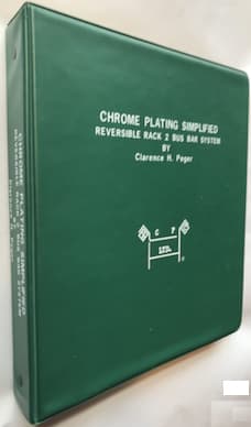
James Watts suggests below that 1/2" distance between anode and cathode is often good. But the design of conforming anodes for chrome plating is an art that people have spent years on; if anyone in your local plating society has a copy of the Clarence Peger book "Chrome Plating Simplified" which Mr. Watts referenced it would be invaluable to you.
Anode-cathode modeling is also a science -- see thread 19693 about electrochemical modeling, and related simulation software.
But send a pic and hopefully someone will help!
Luck & Regards,

Ted Mooney, P.E. RET
Striving to live Aloha
finishing.com - Pine Beach, New Jersey
October 2021
⇩ Related postings, oldest first ⇩
Q. I am a Tool Design engineer with limited experience in designing anodes for plating processes. I need to design an anode for chrome plating a 5.125 inch diameter (outside only)cylindrical part that is 7.50 inches long. The surface area of the part is 120.75 sq in. I plan to surround the part with a cylindrical lead alloy anode. An anode to cathode ratio of 2:1 suggests that the anode inside diameter (ID) should be 10.25 inches. This would place the surface of the part 2.56 inches from the anode ID. Is this correct? If not, my question is how do I calculate the inside diameter for the lead anode for proper spacing with the part?
Asa SmithRobins Air Force Base - US Air Force
2001
|
2001 A. With no more than what was given, this is a piece of cake for conforming anodes. 1. I would certainly use a grid anode rather than a solid sheet. Hard Chrome Consultants in Cleveland sells them. If no one in your shop has their manual, I would certainly buy one. 20% of the book is backslapping and badmouthing regular plating vs conforming anode two bus bar system, but the balance of the book is very down to earth and very useable. 2. It takes more voltage to drive an electron across a distance. This translates into unnecessary heat- A waste of time and money. I would personally set it up with a 1/2 inch spacing. If that seems tight, use up to a 1 inch spacing (part to anode). The tighter you get it, the less voltage you have to apply and the more directional the plate becomes. For a 7.5" tall part, I would use a 6.75 to 7.0 tall anode (grid). This will reduce the dog bone effect that you will get otherwise. Why put on chrome that you have to spend money to take back off and risk burning it because the grinder is in a rush. With a grid, you can nip off every other "post" to further reduce the effective anode area if needed to minorly reduce end overplating. 3. 4.4 to 4.5 volts and a solution temp of 120F will give you an awesome plate rate. 4. Why the grid? Because it percolates a lot better with the outgassing so you get a better agitation and knock down the diffusion layer on the part better. 5. Forget anode to cathode ratio. Anything above 1:1 will not generate much trivalent, so works well. To get more area, the anode has to be further away and is massively less efficient. 6. It works! James Watts- Navarre, Florida A. Using a grid-type anode is preferable because a grid has considerably more surface area than a solid anode the same size. More surface area equals better anode/cathode ratio If you want a good smooth distribution of chrome on the part, use about 1 to 1.25 inches of spacing and if possible, make th anode about 1/2'' shorter than the part on each end, this will slow down the additional plating at the corners for an even distribution. Regards, Phil Sterrettmetal finishing shop - Cleveland, Ohio USA 2001 |
A. Hello:
Interesting question.
I think for such a small part 3 inch spacing is good enough.
But why are you surrounding the part with anodes. You may put flat anodes at both sides. You can move your cylindrical part after some time during plating to avoid any ovality.
Also you should make sure the length of the anodes should be less than the part itself. I would say 1 inch less in your case. Otherwise you will see dogbone effect at the bottom side of the part i.e. deposition build up.
Hope it helps.

Hemant Kumar
- Florida, USA
2001
Q. The suggested anode to cathode ratio is 2:1 or 3:1 now the question is for each and every batch the size of the anode will change so how to design the cathode on which basis?
Aijazullah Tajir- Al-ain, UAE
January 6, 2013
A. Hi Azijazullah. The cathode is the part you are plating; I think you have swapped the words 'cathode' and 'anode' in your question.
Your question is difficult to answer because there are many different ways to fixture parts for chrome plating, and there are many other issues in anode-cathode geometry besides the ratio of the areas. As James Watts has said: "Forget anode to cathode ratio. Anything above 1:1 will not generate much trivalent, so works well."
Are you talking about decorative nickel-chrome plating (which is a different subject than the hard chrome plating process discussed here)? Hard chrome plating can utilize either standard tank anodes or custom made conforming anodes, designed for each individual piece (sometimes built into the rack), but the anodes usually must closely conform to the shape of the part. Please try your best to carefully describe your own exact situation. Thanks.
Regards,

Ted Mooney, P.E.
Striving to live Aloha
finishing.com - Pine Beach, New Jersey
January 6, 2013
by Robert K. Guffie

on AbeBooks
(rarely)
or eBay
(rarely)
or Amazon
(affil links)
Q. I have Cylindrical part OD 38.50 mm & Length 205 mm. I have problem in chrome plating. I have No Idea For JIG & FIXTURE Design for this part.
When I try to do plating to this part/job down side thickness variation. Suggest me How to do plating on this Part.
- Gujrat, India
April 18, 2013
A. Hi Gopal. If designing conforming anodes is outside of your skill set, components of cylindrical shape like that can be (and frequently are) simply plated vertically with tank anodes arranged in a circular shape around them. If the plating is dog-bone shape (thicker at top and bottom than in the middle), the anodes need to be shorter so they don't reach all the way to the top or bottom of the part. Good luck.
Regards,

Ted Mooney, P.E. RET
Striving to live Aloha
finishing.com - Pine Beach, New Jersey
April 2018
Q. Sir,
I have 15 mm dia and 150 mm length cylindrical part for plating hard chrome 6 micron thickness. Anode area is 1400 sq inch and cathode area is 1200 sq inch. What should be ratio for anode to cathode for 1 micron to 1 min deposition
pace auto parts - pune MAHARASHTRA INDIA
April 29, 2018
Q. What is reason behind less deposition rate.
Sudhakar chavan [returning]- Pune Maharashtra India
April 30, 2018
A. Hi sudhakar. Please review our simple explanation of "Faraday's Law of Electrolysis" and you will see that the anode-to-cathode ratio doesn't really come into play in the calculation.
Per the referenced table in the Metal Finishing Guidebook, it takes 51.8 Amp-hours to deposit 0.001" of chrome on one square foot of surface.
This means that to deposit 1 microns (0.0000394") will take 0.0000394/0.001 x 51.8 = 2.04 Amp-hours per square foot, or 122.4 Amp-minutes per square foot at 100% efficiency. You are unlikely to exceed 25% efficiency even with proprietary HEEF-25 or equivalent solutions. So the actual Amp-minutes you would need would be 122.4/.25 = 489 ASF (amps/square foot). This plating rate is probably possible with conforming anodes if you are a crackerjack chrome plater. Good luck.
Regards,

Ted Mooney, P.E. RET
Striving to live Aloha
finishing.com - Pine Beach, New Jersey
May 2018
Q, A, or Comment on THIS thread -or- Start a NEW Thread