
-----
CONFORMING ANODES FOR PLATING? CONFUSED
We run a decorative plating shop and over the years have plated pretty much the same types of automotive parts (bumpers, etc.) now we are seeing more custom built parts that are going to require conforming anodes to get full chrome coverage. The problem is we know nothing about building these anodes and it would not be practical to get anodes built for these parts as we never know just what is going to come through the door . Is there some way to build these anodes from wire and run it into the L.C.D areas , if so what kinda wire ? once the anode is made is it hooked with some sort of jumper wire from the anode bar so when the power is applied the normal anodes as well as the conforming anode plates at the same time ? any and all help is appreciated ....thanks in advance
Marvin Brown- Spartanburg, South Carolina, United States
2003
Conforming Anodes, In decorative chrome conforming anodes, to get 100% coverage you can form an anode(lead) that will represent the part with more concentration on the LCD area and less at HCD area, sometimes it could be just get an extension to the LCD, If large parts you may be able to just reposition anodes to help throw in to the LCD area. Racks can be made where Anodes on the racks insulated from cathode. So basically you are raising the current density to a platable current density,As chrome will not plate in the LCD areas
Chris Snyderplater - Charlotte, North Carolina
2003
![]() A butcher asking butchers how a butcher's knife is sharpened? If anyone with such a limited knowledge in plating can still run a chrome plating shop and make money in the US, certainly makes me as a foreigner think I was born in the wrong country.
A butcher asking butchers how a butcher's knife is sharpened? If anyone with such a limited knowledge in plating can still run a chrome plating shop and make money in the US, certainly makes me as a foreigner think I was born in the wrong country.
Monterrey, NL, Mexico
2003
Maybe you haven't noticed but this website is for the exchange of information and to try and get questions answered from someone with more knowledge of the topic because no matter how much you know or think you know someone always knows more. Trust me, you are in the right country.
Billy Padgett- North Carolina
2003
Q. What would you recommend making these anodes from, some type of wire? A rack would not be practical as we have many different things weekly that require conforming anodes.
Marvin Brown [returning]- Spartanburg, South Carolina
2003
Indeed you were, Guillermo. Haven't you ever heard that the streets of America are paved with gold?
But it is entirely possible for a decorative plater to have plated for a lifetime and never have used auxiliary anodes. I've been to many plating shops that have never used them.
Marvin, Chris' letter really pretty much answers your follow-up. You shape lead into whatever form delivers the required close anode to cathode distance in the otherwise LCD area. You can run insulated copper wire to the lead rather than trying to carry the current down from the tank rims with the lead.

Ted Mooney, P.E.
Striving to live Aloha
finishing.com - Pine Beach, New Jersey
Ted can be retained for immediate
answers or long term project help
2003
Our friend from Mexico is a bit crude in his response, but he is correct. Every shop has significant differences. We cannot possibly offer recommendations with out a great amount of additional information. I assume that you are using tank anodes now. When you consider that the "throw" is related to the square root of the distance from the cathode to the anode, an auxillary anode will throw a great amount of chrome relative to the anode. Translated, you will have a very large amount of trial and error before you get it right. Me, I would use a heavy lead wire/rod to maintain the rigidity. Shape has a massive amount to do with the direction the plating throws. You will probably have to hire a consultant, and that will be a problem since he will see a different set of parts each day, which makes optimization difficult. If all you need is a little amount of help in select areas lead wire should work. Remember, the rod will change position as it warms up in the tank. I am a strong proponent of conforming anodes, which plate at warp speed and higher efficiency compared to tank anodes. Drawback is that you need a lot of anodes to fit a wide variety of parts.
James Watts- Navarre, Florida
2003
A. Dear All,
Much said already, so here's another tuppence worth. Ingenuity is the other side of the coin of ignorance! I think the question had its answer in it in the first place. Ever been to Indian plating shops? Some of the most ingenious ideas spring from guys who aren't supposed to have em!

Khozem Vahaanwala
Saify Ind
Bengaluru, Karnataka, India

2003
2003
![]() I see that that most dismal of all management theories, Management by Objectives, hasn't infected your subcontinent, Mr. Vahanwala :-)
I see that that most dismal of all management theories, Management by Objectives, hasn't infected your subcontinent, Mr. Vahanwala :-)
Good ideas should be welcomed wherever they come from.

Ted Mooney, P.E.
Striving to live Aloha
finishing.com - Pine Beach, New Jersey
Ted can be retained for immediate
answers or long term project help
A. Platinised titanium is the best anode material for your application.
Vanajambika Jeyakumar- Chennai
2004
May 28, 2008
Lead anodes are the pick of choice because of simple conductivity issues that may arise.
After watching the news, you may not need this advice after all.

Ryan Cook
Toccoa, Georgia
The Physics of Conforming Anodes
November 8, 2015Q. Hi
I am interested in conforming anodes and in the background physics although I do not claim any expertise.
I was fishing around online in the hope of finding software simulations, perhaps simply 2D dimensional that might give a handle on current distributions. I have yet to find (free/cheap) software specific to current density in ionic solutions but I did find a general field simulator for charges -- it's online and free to use.
http://www.flashphysics.org/electricField.html
I used the tool as follows.
1. I constructed a 2D bowl, well actually a cross section though a bowl I want to plate the inside of,
I used the grid option and placed - charges closely spaced along a profile I judged to approximate the cross section, all a matter of judgement and eye.
2. In the first pass I constructed a flat + charge anode a distance away from the bowl cross section.
It looked something like this... C |
So a set of - charges shaped like a letter C for the cathode and a set of + charges along a straight line for the cross section of the anode.
3. In the second pass I constructed a conforming anode - something like a small C inside a bigger C, concentric half circles if you like although my bowls are precisely that shape.
I used the Equipotential setting, so that the density of lines shows the potential gradient - more ions should flow when the lines are bunched (similar to a map showing a hill, you roll down hill fastest where the contour lines are closest to one another!!!)
The controls take ten minutes or so of fiddling to master, you can place charges, move them and alter their polarity.
Whether or not 2D electrostatic charges and associated fields make for a good model of current flow in ionic liquids I am not sure, perhaps others might comment, at this stage I just wanted to play and see trends and patterns.
Certainly the equipotential picture I built up of my "bowl" seemed to make sense compared with practical results for me, it predicted very dense equipotentials around the rim of the bowl and quite a drop off towards the centre of the bowl.
Even though the region just inside of the rim is almost 90 degrees to the flat plate anode it actually receives the bulk of deposited metal!!
However when I saw the equipotential and field lines around the rim region I could see an explanation as the equipotentials clustered very close to one another in the region of the rim and importantly the field lines were very curved here suggesting that ions traveling almost parallel to the rim region would swing around through nearly 90 degrees in the last part of their journey and actually hit the rim region square on. This is what I see in practice, despite the fact that the rim region is pretty much at 90 degrees to the flat anode it receives a heavy dose of metal.
Equipotentials were much more widely spaced towards the centre of the bowl offering an explanation why despite being square on to the flat anode the centre of the bowl received far less deposited metal.
Its hard to put into words but basically interpretation of equipotential and field lines offered me explanations that correlated well with what I am seeing in practice.
I will be moving on to experimenting with "spaghetti" conformal anodes as described here...
http://www.plating.com/platingtechnical/anodetypes.htm
Anyone know of free/cheap software that might help model conforming anodes - at least in 2D profile?
I am interested in leads or opinions on the interplay between
1. Agitation -- ions apparently move quite slowly so agitation is significant in uniform ion density with no depleted regions.
2. Boundary layer and its effects.
3. Field or current density and distribution.
As far as I understand it agitation is all about keeping a uniform ion density, however once that is taken care of then the rest is mainly about current density and distribution?
- Saltum Denmark
November 9, 2015
Q. My second post in a few days, this follows my interest in seeing if electrostatic field software can be used to give an indication by trial and error simulation as to ideal anode shape.
The part to be plated is the interior of a bowl - to an approximation I will say its a hemisphere.
The exterior is masked off.
In the end I used my metal spinning lathe and made a conforming anode which is also close to a hemisphere and around half the diameter, not
an easy spin since the sheet copper is over 2 mm thick.
I am plating copper (copper acid).
Much better results than previously obtained with flat anodes.
The main defect is still a very heavy plate around the inside of the rim but the entire inside surface is well plated.
Interestingly enough the static software suggests that even with this kind of shaped anode it is very difficult to relieve the very high field gradient near the edges of a bowl like this, these experiments are suggesting that the rim of the anode needs to retreat further towards the common axis so that is more distant from the rim.
Interested in any observations or ideas from others.
Still not sure that application of static electric field software is actually relevant but so far it does seem to be leading me in the right direction and explaining what I see in practice.
- Saltum Denmark
November 2015
A. Hi Jon. There are at least a couple of vendors of electrochemical modeling software, but it's presumably far from free, and I haven't seen it in operation.
It doesn't surprise me that the rim area gets heavy plating even when 90° to the anodes because I don't think the ions have much momentum.
Two notes which you may already realize ...
1. Agitation serves at least 3 purposes. One is solution homogeneity, and a second is temperature consistency. But a third can be to thin the boundary layer for faster plating. High-speed plating machines sometimes shoot a jet of plating solution at the surface being plated. It doesn't change Faraday's Law, but it allows much greater current density without "burning".
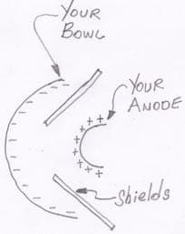
2. Another, sometimes simpler, tool to directing where the current flows is "shields" -- nothing more complex than a piece of plastic inserted somewhere between the anode and cathode so the shortest path is blocked.
Luck & Regards,

Ted Mooney, P.E. RET
Striving to live Aloha
finishing.com - Pine Beach, New Jersey
Ted can be retained for immediate
answers or long term project help
November 11, 2015
Hi Jon
This subject is in the realms of electrochemistry rather than physics.
If you trawl through the annals of the Transactions of the Journal of the IMF you will find a number of articles on this subject using finite element analysis. All very learned and academic but in 50+ years in electroplating I have never seen it successfully applied in practice. There are too many variables.
Experience and experiment along the lines suggested by Ted are much faster and more likely to succeed.
Two points that may help.
Acid copper has rather poor throwing power unless you use one of the additives developed for the printed circuit industry.
Some edge build up is almost inevitable. One solution might be to make the hemisphere oversize and turn off the rim.

Geoff Smith
Hampshire, England
November 13, 2015
Q. Hi Geoff
Thanks for the reply and advice - also thanks to Ted for his suggestion of shields.
Electrochemistry or Physics? I know a lot of Physicists who regard the study of moving charges in electric fields as their turf but sciences are interconnected and boundaries diffuse. Physicists do have a habit of thinking everything ultimately boils down to Physics which probably irritates the chemists :-)
Its interesting that in your extensive experience you have not seen FEA applied successfully to this area, having said that I am using the online software previously mentioned to try and see patterns and shapes, nothing quantatative and it did for the first time give me an impression of what might be going on so in this regard I do think it was very useful just to give an indication or picture but I am sure you are right in terms of usefulness beyond that.
For me it helped in the sense that I felt I was not groping in the dark but instead had a picture in my minds eye what the problem might be, indeed I was already thinking in terms of the kind of shielding Ted suggested so in that sense a picture did seem to help decide what the next step should be.
If Ted will indulge me I will make up some pictures to add to this post to help illustrate. I think its worth underlining again however that this software is intended to show static charge fields and the link or usefulness to ion migration in water is not proven and aspects such as agitation will affect boundary layers and hence how charged particles react to a field, even if the picture of the field is representative there would be other factors for sure.
As far as I understand it ion migration velocity is very slow and much slower than agitation speeds which suggests to me that agitation would not actually affect the current density pattern very much other than to reduce boundary layer depth and ensure bulk mixing and uniformity so that otherwise stagnant areas do not become depleted and hence cause burning.
Anyway back to the test rig -- been building a new one the last few days to try out shielding.
- Saltum Denmark
![]() Hi Jon
Hi Jon
Most chemists are amused rather than irritated.
While physicists are debating the fate of Schrodinger's cat, the chemist simply places his nose near the box. The smell of cadaverine is quite distinctive. NH₂(CH₂)₅NH₂

Geoff Smith
Hampshire, England
November 14, 2015
A. Hi Jon
I just want to mention you a current stealer made of copper wire which present at the rim position may also work effectively like shields to help reducing the extra build up.
I'm working on high temperature chemistry, using chemical vapor deposition method to build coating for gas turbine blade which needs both theory support and experiment to verify ideas.
Hope you can solve this problem theoretically and practically.
Institute of metal research - Shenyang, China
November 16, 2015
November 21, 2015
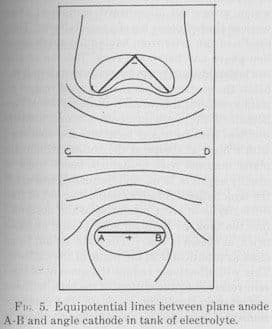
Q. Hi, still on the topic of this online tool for showing equipotentials
I was interested to see within Grahams Electroplating Engineering Handbook p.465 a diagram showing equipotential for an angle shaped cathode and plate anode.
This encouraged me to compare the diagram he came up with with a simulation using the software.
pic1, fair correspondence with Graham's picture:

The second picture, pic2 shows my current state of play with the bowl shape ( plating inside only ), simulations have lead me away from an equidistant conforming anode ( another hemisphere) towards more of a rounded tear drop. I really want to pull current density away from the rim region.
I have yet to try this out as my first conforming anode was produced on my metal spinning lathe, the rounded teardrop does not lend itself to that method so it will take time to turn conjecture into practice.

For any readers not familiar with this kind of diagram, we are showing lines of equal voltage in a cross section of the anode and cathode, it is assumed they are in vacuum so here we are seeing the bare field patterns as dictated purely by the cathode and anode shapes.
Limitations: Even if Graham is correct in his application of equipotentials there are some notable limitations with this software.
1/ We are modeling continuous materials with point like charges.
2/ This does not allow for increased charge density as you might find at the tip of a sharp point although there is nothing to stop you raising the charge of a final dot to a higher value if you have a gut feeling it might be double or triple.
Even given these limitations I am still using the software with caution as a kind of broad strokes picture of what might be going on, a picture even crudely drawn can still be worth a thousand words, certainly playing around, seeing patterns and trying scenarios has been responsible for my shift from the hemispherical anode to the rounded tear drop one so I feel it can help bring ideas to the surface.
Ideally I would like to find free software that could model continuous substances (i.e., not just approximating by point like charges ) and the software does have limitations in that one cannot save work, etc.
- Saltum Denmark
Designing of conforming anode for platinum plating on a complex shape part
November 23, 2015Q. Dear all
I am designing a conforming anode for platinum plating on industrial gas turbine blade, because extra platinum is built on the edges during plating due to its complex shape.
I am using the 5Q salt from Johson Matthey, maintaining a temperature of 92 °C, pH 10.5 and CD ranging from 0.4 - 0.6 A/dm2.
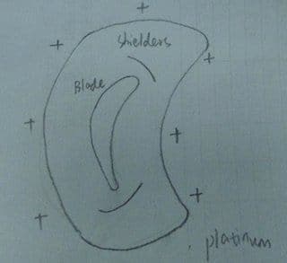
The anode material that I use is pure platinum wire gauze and I have two candidates.
See picture:
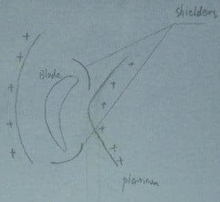
The first one is two gauzes which are bent to fit either side of the blade to make sure distance between anode and the blade is 1" to 1.5", and two shields made of teflon protect the edges from the current gathering.
Second one is a bigger circle around the blade and the distance is also 1"to 1.5".Shields to be put at the same position as the first one.
Any suggestions on which one is suitable? Or maybe none.
chemical engineer - Shenyang, China
Q, A, or Comment on THIS thread -or- Start a NEW Thread