A Practical Guide to Understanding, Measuring and Controlling Stress in Electroformed Metals
( Paper presented at the AESF Electroforming Symposium, March 27-29, 1996, Las Vegas, NV
and reprinted at www.finishing.com through kind permission of
AESF )
By B. Stein, CEF
NiCoForm

STRESS (Noun) : The act, condition, or effect of exerting force on someone or something. Roget's Electronic Thesaurus

The stressed nature of electrodeposits was first recognized in 1858. Extensive theoretical and experimental studies in the origin and nature of stress carried out since in many parts of the world have produced surprisingly few sound guidelines for the practicing electroformer. This paper will attempt to summarize the most important findings of past research and suggest practical steps for successful stress control in electroforming.
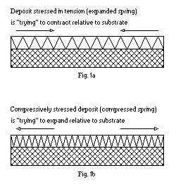
A simple analogy can be used to demonstrate the difference between tensile and compressive stress - the two practically important types of internal stress in electrodeposits. Deposits having tensile internal stress can be thought of unidimensionally as a stretched coil spring or rubber band (see Fig. 1a), attached to a stress-free
(before deposition) substrate. Compressively stressed unidimensional deposits, then, will resemble a compressed spring (Fig. 1b) attached to the substrate.

Since real deposits always form in two-dimensional layers, the unidimensional model of stress is but a convenient scientific abstraction. Yet, it can help illustrate that, just like a spring, a stressed deposit displays internal elastic forces causing it to expand or contract if the bond between the substrate and the plated layer can be broken. Whenever the adhesion to the substrate is strong, the latter, depending on its thickness and elastic properties, will be distorted to a convex or concave shape and partially relieve internal stresses in the deposit. This phenomenon has been successfully utilized by Stoney(1) who developed on its basis an extremely sensitive method for measuring internal stress in plated deposits known as the bent strip (cantilever beam) technique.
Given the tendency of stressed electrodeposits to expand or contract once the bond between the deposit and substrate is broken, difficulties facing practicing electroformers are quite formidable. Even moderate (7,000 -10,000 psi) tensile or compressive stresses in electroforms may lead to geometric distortions and loss of reproduction fidelity. Stresses in electroforms may also result in form "shrinkage" or warping causing difficulties in mandrel separation after forming, often referred to as "locking". In more severe cases, higher stress levels will result in spontaneous early form-from mandrel separation, leading to loss of form and/or mandrel. Extreme stress levels in electrodeposits are known to cause metal cracking. Processes with such high deposit stresses are, therefore, not suitable for electroforming. In cases where post-machining of electroforms is required, additional difficulties may arise due to machining heat effects. Those may cause further electroform distortion or damage if substantial residual internal stresses are present.
The foregoing, then, leads to a logical conclusion: successful electroforming depends on our ability to measure and control stress during electrodeposition.
Stress Measurement Techniques
A number of modifications to the original bent strip test method, mentioned earlier, found their way into the research laboratory over the years(2). Other methods were also developed. The spiral contractometer was invented by Brenner and Senderoff(3) in 1949, Kushner's stresometer(4) - in 1954. In 1958 the length-change
(dilatometric) stress determination method was proposed by Popereka(5.) An electronic strain gauge apparatus6 constituting a modification of the stresometer concept was patented in 1985. All of these as well as the more recent optical (laser and interferometric) techniques have been used for laboratory studies of stress during electro- and electroless deposition.
For a test method to be accepted and routinely used in an industrial environment, as opposed to a research laboratory, a number of fairly stringent additional requirements need to be met. First and foremost, the test has to be fast, simple to use and interpret, the equipment - reliable and robust, the results - accurate, repeatable and meaningful. In the case of electroforming it also means, for reasons to be discussed later, that stress tests must be performed directly in plating tanks in a non- or minimally invasive fashion. This last requirement simply means that carrying out a stress test should not significantly alter the established electrochemical or hydrodynamic patterns in the process tank. The ability to take measurements continuously and ease of automation are also desirable features for an industrial stress measurement method.
Most of the known today stress testing methods fail to meet at least one of these requirements and, therefore, are suited more for laboratory than for industrial use. So, the spiral contractometer is bulky, requires calibration prior to each test and deposit stripping afterwards. The two disk membrane devices - the stresometer and its electronic modification are fairly complicated yet not sensitive enough in the low stress level region (1,000 psi) and require periodic deposit stripping, too. The same is true about the dilatometric stress measurement method, whose accuracy is additionally affected by temperature variations.
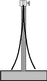
The nature of electroforming itself dictates that of most practical interest to the process engineer should be low stress levels which, as noted earlier, cause the least distortion in the electroform. With this in mind, the simplest yet sensitive enough measurement technique for industrial applications is still the bent strip method. One of it's present commercial versions(7) utilizes disposable brass two-legged strips whose opposite sides are plated and the resulting leg deflection caused by deposit stress is measured on a simple scale
(Fig. 2).

Fig. 2
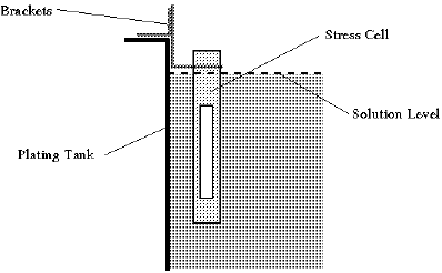
A formula is used to convert units of spread into the deposit stress level. Tests can be performed directly in the plating tank by using a slotted tubular cell (Fig. 3) which has the added advantage of precluding any possible errors during electrolyte transfer to a laboratory cell through dilution, contamination, temperature variations, etc.

Fig. 3
Stress Control Techniques
The numerous published theories of stress in electrodeposits seem to agree on one point: it is hard to find a process variable that does not influence deposit internal stress. Indeed, internal stress is perhaps the most integral characteristic of an electrodeposition system. A typical list of variables affecting internal stress in a deposition process usually looks like this:
-
- 1. Current density;
- 2. Concentration of every major component of the plating bath
(metal salts, conductive salts, buffering agents, wetters, etc.);
- 3. Concentration of additives (organic or inorganic);
- 4. Concentration of impurities (chemical or particulate), including trace amounts;
- 5. Bath temperature;
- 6. Agitation rate;
- 7. Solution pH;
- 8. Plating cell geometry;
- 9. Composition and condition of anodes;
- 10. Anode/cathode surface area ratio;
- 11. Quality of DC power (ripple);
- 12. Nature and condition of the substrate;
- 13. Numerous others.
This seemingly endless list of factors may make any attempt at stress control look futile at best. And yet, a methodical approach coupled with tight process control and good housekeeping makes stress control during electroforming perfectly possible. An important note to make here is that a particular plating tank represents such a unique combination of variables listed above, that it is preferable to measure stress directly in the tank rather than hope to recreate the same conditions in a laboratory cell.
A somewhat closer look at the list of variables above will reveal that at least some of them are either constant for a particular plating process/tank combination, or can be kept constant with relative ease (concentrations of main components, temperature, pH, cell geometry, anode/cathode ratio, agitation). Once a particular plating chemistry has been selected and initial process variables fixed, one needs to map an important process baseline - the bath stress profile. Stress profile is the relationship between deposition current density and the corresponding deposit internal stress. This can be easily established by repeating a stress test several times at varied current densities keeping the rest of the variables constant. Sample stress profiles for several sulfamate nickel electrolytes are shown in Fig. 4.

Fig. 4
After the base chemistry stress profile has been established, it is important to define effects process variables have on it. Solution temperature increase, for instance, in a sulfamate nickel bath, will shift the entire stress profile curve lower, towards the more compressive values. Once such understanding has been gained for all or at least a few critical variables, it is relatively easy to optimize the process for the most desirable stress profile, the highest possible plating rate or any other objective. A useful outcome of this part of the study will also be the distinction between critical and trivial process variables in terms of stress control.
Naturally, for this effort to be worthwhile all work needs to be done in a system that is known to be free from impurities and otherwise representative of the process.
The second important characteristic an electroformer needs to be aware of is the process window, or the range of internal stress levels within which parts can be successfully electroformed. This should be established empirically, but is well worth the effort and expense of doing. Comparing the process window to the bath stress profile will help define the appropriate current density range for successful electroforming and give an overall process estimate in terms of its suitability for a given task. Processes with steep stress profiles are usually less suitable for electroforming, while a relatively flat stress-current density curve makes for an easy and versatile operation.
Armed with the knowledge of the optimized process stress profile and the process window, one can now determine how s/he wants to control stress in the system. Decisions need to be made as to what variable(s) to use for stress control, what level of stress to maintain at what current density, and how frequently to measure and adjust stress in the bath. It is easy to see that the process window defines the desirable internal stress range.
The number of ways people control stress during electroforming is as great and diverse as the number of variables that affect it. Among the most notable methods are: average current density adjustment during deposition6 , temperature adjustments, addition of organic stress-reducing agents8 such as saccharin and naphthalene-sulfonic acid derivatives, varying solution agitation rates, etc. It is imperative in this approach that all process variables except for the control ones should be kept constant, while the control variables are changed only in response to observed stress changes in the system. A sophisticated computerized stress control system6 based on these principles has been successfully implemented in an industrial application.
Regardless of the chosen method of stress control, it is important that stress readings in the process are taken and adjustments to control variables are made as needed to maintain the desired stress level at regular intervals. These intervals can be established once an evaluation of the rate of stress variations in the system has been made. Regular stress measurements will also help detect increased levels of contaminants in the bath or other process deviations that usually result in abrupt unexplained stress changes.
The outlined approach to stress control during electroforming does not exhaust all the possibilities at our disposal. Even processes with relatively high as-plated internal stress levels can sometimes be successfully used for forming objects with tight dimensional tolerances. This can often be achieved, as long as the electroform does not loose its integrity in the process, by appropriately heat treating the finished form prior to removing the mandrel. In many instances, stressed electrodeposits will respond to heat treating in a fashion similar to cold worked metals. A complete progression from normalization through stress relief and recrystallization to full annealing can be observed in sufficiently pure electrodeposits.
Another sometimes practiced procedure for removing stressed forms from reusable mandrels includes heating or cooling the electroform/mandrel assembly so as to facilitate their separation due to unequal coefficients of thermal expansion. Obviously, this method will not assure dimensional stability of the form after separation.
Conclusions
Despite the multitude of factors affecting stress in an electrodeposit, stress control during electroforming can be successfully implemented once a clear understanding of the bath stress profile and the process window have been developed. Regular stress measurements, good housekeeping to prevent bath contamination and deliberate selection of control variables for stress maintenance are critical to the success of this approach. Post-plating heat treatments can be useful in reducing stresses in electroforms with high internal stresses.
Acknowledgments
Thanks are due to my friends and coworkers at Reflexite PTC for the stimulating atmosphere of creativity and constructive criticism and to Reflexite Corporation for the permission to publish this paper.
References
-
- 1. Stoney, G.G., Proceedings of the Royal Society, A82:172; 1909
- 2. Armyanov, S. and Sotirova-Chakarova, G., Metal Finishing, 90:61, November 1992
- 3. Brenner, A. and Senderoff, S., J. Res. Natl. Bur. Std, 42:89, 1949
- 4. Kushner, J., Plating, 41:10, 1954
- 5. Popereka, M. Ya., Vnutrennie Napryazheniya Elektroliticheski Osazhdayemych Metallov. Novosibirsk, 1966
- 6. U.S. Pat. No 4648944
- 7. Dini, J.W.,
Electrodeposition, Noyes Publications, 1993
- 8. Watson, S. A., Additions to sulphamate nickel solutions, Nickel Development Institute, 1989
Back to finishing.com Home Page 