
Curated with aloha by
Ted Mooney, P.E. RET

The authoritative public forum
for Metal Finishing 1989-2025

Thread 97/55
Gold Plating on Copper: Diffusion barrier needed?
Q. Hello,
I am a student at Northwestern University in a Physics lab and am trying to electroplate gold onto a copper piece. I have a few questions about the process.
1) What voltage and current should be used to plate the gold, about 0.001" - 0.002" thick onto the copper? The area of the copper piece we wish to cover is not more than 0.700". How long would it take (approximately) to plate that much gold at the specific voltage and current?
2) What is the anode to cathode ratio given by some suppliers of gold electroplating solution? Does it mean the mass ratio of the solid metal at the anode (gold) to cathode (copper)? If for my specific electroplating solution it says this ratio is 2.1 does it mean I need 2.1 times as much gold at my anode as copper at my cathode?
3) What is a good way to mask parts of my copper piece so they do not get plated? Would masking tape work since it is not a conductor or will the conductivity of the copper still attract gold through the tape and onto it?
4) Do I need to cover the anode piece in cotton? I've read this needs to be done to keep the solution there.
Thank you,
student, Northwestern University - Evanston, Illinois, USA
2005
publicly reply to Sam Blinstein
A. Two specific suggestions:
1. Go to the library and seek out a good electroplating reference, like the Metal Finishing Guidebook, Modern Electroplating, or Electroplating Engineering Handbook ⇦ this on
eBay,
AbeBooks, or
Amazon [affil links]
. Some of the answers to your questions depend on the gold bath formulation.
2. It is usually bad practice to plate gold directly on copper, as the two metals will form a solid solution. Generally, a nickel barrier is plated between the copper and gold.

James Totter, CEF
- Tallahassee, Florida
publicly reply to James Totter, CEF
by Reid & Goldie
-- hard to find & expensive; if you see a copy cheap, act fast!

on eBay or
AbeBooks
or Amazon
(affil links)
A. Hi Sam,
To answer some of your questions:
1) I'm a metric man and don't want to have to think in those units so I'll leave this to someone else :-)
2) No one uses solid gold as anodes. just use some platinized titanium, these won't dissolve nor (obviously) replenish the gold being plated out of the solution so this is added back as a gold salt. The ratio is a AREA ratio not a mass ratio. usually 2 to 1 or higher.
3) Masking lacquers and tapes are common ask the supplier that sold you the gold solution for something.
4) The cotton is used to prevent solid chunks of anode falling off and plating as roughness on your part, but if you use the anode I mentioned above that doesn't dissolve and this is not an issue.
5) Did you know that gold over copper will tarnish! The copper diffuses into the gold to create an alloy and can appear spotty. Usually a thick barrier layer (sometimes of nickel plating) is applied between the two.
good luck and beware of the cyanide
- Melbourne, Vic, Australia
publicly reply to Peter Van de Luecht
A. Hi Sam.
Please see also the article "" in our on-line librry
1. If the area of your component is 0.7" inches^2, and the desired plating thickness is 0.001", then you want to deposit 0.0007 inches^3 of gold. Let's switch to metric at this point and call it 0.0115 cm^3. Gold weighs 19.3 g/cm^3, so you want to deposit 0.222 grams of gold.
If your gold bath is based on gold potassium cyanide, K+Au+(CN)-2, then the oxidation state of the gold is Au+1. This means if you pump one electron from the anode to the cathode with your power supply, one ion of gold will come out of solution and become an atom of gold on the cathode. Cutting through some of the conversion factors, Faraday's Law of Electrolysis says that one Faraday (96,485 coulombs or ampere-seconds) will deposit one gram atomic weight. Since the atomic weight of gold is 197, one Faraday deposits 197 grams. So to deposit 0.222 grams requires 0.01127 Faradays or 108.7 ampere-seconds.
In practical gold plating, though, not all 100% of the applied electricity deposits gold; some (maybe 10%) is wasted to the hydrolysis of water into H and OH. So, say it will actually require about 108.7/0.9 or 120.8 ampere-seconds to deposit your gold. Continuing with some empirical issues, you'll find that your current density for satisfactory plating will be limited to about 4 amperes/ft^2, which is 0.0278 amperes/inch^2, or 0.0194 amperes on your piece.
Thus to apply 108.7 ampere-seconds at a rate of 0.0194 amperes will take about 5600 seconds -- roughly an hour and a half.
2. As previously mentioned by Peter, the anode to cathode surface area should be about 2:1, which means your anode area should be about 1.5 inch^2
3. The easiest approach to very simple masking is "plater's tape". This is very similar to electrician's black vinyl tape except a bit thicker and with extra care given that the materials used are compatible with plating.
4. Peter has given one explanation of the cotton, but I'm thinking it is possible that you were reading about "brush plating". In that approach, rather than immersing your part and the anode into a small vat of solution, the anode is equipped with a sock-like cloth cover which is soaked with the plating solution and brushed onto the cathode. I don't think that's what you are looking for though.
Please note that this theoretical discussion should not be read to imply that working with poisonous cyanide solutions is safe (it isn't!), or that the plating is easy. Typically, parts should be sent to specialty plating shops to have the plating applied to them. Good luck.
Regards,

Ted Mooney, P.E.
Striving to live Aloha
finishing.com - Pine Beach, New Jersey
publicly reply to Ted Mooney
Q. I am an engineering student and I am new to "Gold Plating". We are trying to "plate" a copper shim (.006 thick), and we are afraid that the gold will attack the copper (galvanic corrosion). I believe that we need some sort of "plating" between the two. Also we are unsure of the thickness for the gold, I am being advised by our vendors that anywhere between 10 and 300 microns (what a range) would suffice. This part will be used to raise a current high power device to the height of a PCB.
Robert Moore- Belmar, New Jersey
2001
publicly reply to Robert Moore
A. You won't get galvanic corrosion, but the copper will form a solid solution with the gold. Normal practice is to plate nickel over the copper to prevent this, .0003" should be sufficient.

James Totter, CEF
- Tallahassee, Florida
publicly reply to James Totter, CEF
2001
A. You do need an interlayer of nickel plating, but not as a guard against galvanic corrosion, but rather to prevent the gold from diffusing into the copper.
The 10 microns sounds more reasonable than the 30, but 10 microns is still very heavy for gold plating in an application like this. Perhaps the recommended range was 10 to 300 microinches rather than micrometers? Then I'd say 10 microinches is very thin and acceptable only where very good testing and process control is possible, whereas 300 microinches is probably overkill, and a realistic range for your experiments would probably be 30-100 microinches.

Ted Mooney, P.E.
Striving to live Aloha
finishing.com - Pine Beach, New Jersey
publicly reply to Ted Mooney
A. Gold can be plated directly over copper but the copper will migrate into the gold layer over time. Copper is usually plated with nickel before being plated with gold and gold can be plated to almost any thickness from only a few micro-inches up to whatever thickness you are likely to want.
Neil BellAlbuquerque, New Mexico
publicly reply to Neil Bell
Q. For over 15 years, Molecu Wire has plated gold directly onto 0.004 inch diameter OFC copper wire for the computer industry.
This wire is used to connect the read/write head to a terminal strip attached onto the suspension arm in a hard disk drive.
Billions of feet have been used in this application.
No nickel underplate was ever applied!
IBM was our first customer ... and was our last until just some months ago (these discrete wires are now replaced by high density flex circuitry).
Yes, the nickel inhibits diffusion. Yes, nickel underplate is SOP for connectors, pins, etc.
Yet - no one has yet to tell me why no nickel was necessary for this hard disk drive application, especially since this wire is the "first" wire to be seen by any data coming into the computer from the data storage device media! -- a rather critical place, I would say.
Regarding diffusion time - it is my understanding that, at room temperature plus, detrimental effects due to diffusion would occur in a period of time which exceeded the product lifetime.
Comments from others are invited.
New to your fine group,
Stephen TetorkaMolecu Wire Corporation - Farmingdale, New Jersey
publicly reply to Stephen Tetorka
A. You'll have to do a recall on every inch of those billions of feet, Mr. Tetorka :-)
Only kidding, of course; thank you for sharing some very practical knowledge with us. We have a paper on Nickel Diffusion Barriers in our on-line library [www.finishing.com/library/stransky/nidifbar.html] that you might find interesting. Is it possible that the reason for the gold plating was solderability or wire bonding, or something which is done early in the life cycle such that longer term diffusion is of no consequence?

Ted Mooney, P.E.
Striving to live Aloha
finishing.com - Pine Beach, New Jersey
publicly reply to Ted Mooney
A. One reason for eliminating Ni underplate is Ni magnetic properties. It will mess up in the areas where magnetic field measured or sensed.
Mark Ayzenberg- Hudson, New Hampshire
July 16, 2012
publicly reply to Mark Ayzenberg
Q. I need expert advise on the preferred Ni barrier thickness (max. and min.) between Au plating and Cu substrate. The end application is AuSn eutectic solder die attach on the Au surface. Can some one help me? Thanks in advance.
Vic Teohengineer - Malaysia
September 4, 2013
publicly reply to Vic Teoh
Solder IMC separation
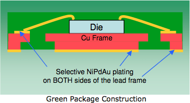
Pre-Plated Lead Frame
Courtesy:
Possehl Electronics⇩
Ed. update: The above link is broken. Thankfully, the Internet Archive preserved a copy here ![]()
Please consider a donation to The Internet Archive.
Q. Hi,
We are manufacturing NiPdAu PPF lead frame. We are facing two issues:
1. Currently we are facing solderability issue. We are observing non wetting where Au & Pd layer still remained on the surface of the non wet area. what could be the potential and how to resolve this? Flux used is Rosin Mildly Activated & Solder Lead free.
2. We are also having an IMC separation issue where SEM shows gap between Solder & Ni.
EDX in between gap shows C & O. What could be the potential issue? Ni thickness ~ 30 µ", Pd ~1.6 µ", Au ~0.2 µ"
Lead frame plating shop employee - Bayan Lepas, Penang, Malaysia
September 4, 2013
publicly reply to Adam Aizuddin
A. Hi Adam,
Solder non-wetting on PPF leadframe, among others things like soldering temperature, solder paste/flux quality, etc, could be due to poor plated Pd/Au purity and/or morphology. Metal source like palladium solution and gold salt must be of high purity while proprietary additive/replenisher should be analysed and added according to chemical supplier recommendation.
For IMC separation, usually C & O could be detected by EDX to certain extent which is common unless C and/or O is abnormal high. The separation could be due to inadequate intermetallic layer formation, improper soldering temperature profile, nickel oxidation prior Pd/Au plating, etc.
Regards,
David

David Shiu
- Singapore
publicly reply to David Shiu
Gold plating directly onto Copper
Q. Hello, I am interested in plating gold directly onto a copper substrate. I want to take advantage of the diffusion of copper into gold for increased adhesion properties BUT, I don't want the copper to diffuse completely through the gold. Is there a certain thickness of gold that can be placed to ensure the copper doesn't diffuse through?
Thanks,
Joel
- San Diego, California, USA
March 18, 2014
publicly reply to Joel Hirschkoff
A. Joel,
What is the maximum temperature? This information is crucial to the calculation.

Blake Kneedler
Feather Hollow Eng. - Stockton, California
publicly reply to Blake Kneedler
Q. Hi, regarding the use of a nickel barrier layer between gold and base copper on a PCB, is there any data available that gives a maximum storage time at normal office temp & humidity before gold wire bonding is performed?
Soft gold thickness will be 3-4 µm over 3-5 µm of electrolytic nickel. I appreciate that the gold should not deteriorate but I have heard that over time copper and even nickel can migrate up to the surface which would cause bonding problems.
- Chelmsford, ESSEX, U.K.
April 17, 2015
publicly reply to Trevor Barrett
Q. Can you tell me exact procedure for coating gold on copper with chemicals, concentration, time and volts?
Sravan Chowdary Talasila- arlington,texas, usa
July 1, 2015
publicly reply to Sravan Chowdary Talasila
A. Hi Sravan. The first thing to realize if you are new to this is that few people (except Ph.D. students for a thesis) attempt to formulate a gold plating bath from raw chemicals; most just purchase proprietary formulations that have been developed over the decades.
The next thing to realize is that there are many different general types of gold plating solutions for electrolytic plating: alkaline cyanide baths, old-fashioned ferrocyanide, neutral cyanide, acid cyanides, citrates, sulphites; hard and soft golds; pure and alloyed golds; bright and matte golds depending on the relative importance of appearance, hardness, freedom from porosity, wear, solderability, tarnish resistance, etc.
If you can introduce yourself (hobbyist, high school student, post-doc) and what it is that you wish to gold plate, and why, I think our readers would be able to distill it down to some basic instructions of what you would need to do to apply gold electroplating to a properly prepared substrate. Thanks.
Regards,

Ted Mooney, P.E. RET
Striving to live Aloha
finishing.com - Pine Beach, New Jersey
publicly reply to Ted Mooney
Q. Hi,
I am working on an application which requires a machined part to have the highest possible electrical conductivity, but also must resist tarnishing or oxidation. At the moment, I am considering C360 brass and C101 copper. Either would be finished with gold plating. If the diffusion of copper does not impact conductivity, and only impacts appearance (color), that would be fine in my application. If it will lead to oxidation over time, and brass would not, then I would choose brass. If a nickel under-plating would impact conductivity, I would likely choose brass. Service life of the part is 3-5 years. Storage and use temperature would be ambient.
Thanks
Justin
- Poughkeepsie, New York, usa
January 27, 2017
publicly reply to Justin Divalentino
A. Hi Justin
You are not clear if the part itself has to have conductivity or are you designing a contact.
In the first case it is unlikely that the plating will make any difference as the part carries the current.
If the part is a contact, you have many more questions to ask.
Is it a sliding contact with many insertions or a plug and forget? What is the contact pressure etc. Voltage, current etc ?
The service atmosphere is important because the limiting factor is not diffusion but porosity in the gold plating allowing corrosion.
In the long gone days when gold was $35 per oz. specs regularly called for 5 microns minimum of acid hard gold. Top military specs are now half that or less over about 5 microns of nickel. If your application really is critical you also need to specify porosity testing of the finished part.
If you are not asking these questions, I cannot believe that your application is truly critical by aerospace/military/ medical standards.

Geoff Smith
Hampshire, England
publicly reply to Geoff Smith
Cause of green corrosion in copper switch
Q. Hi. I've a question and this thread looks to be the closest I've come to finding an answer.
I've got a dual action pushbutton switch and found a green residue between the contacts of this switch along the insulation barrier. I'm investigating whether the switch was in fact short circuited due to water ingress at one point.
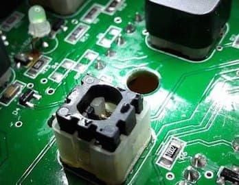
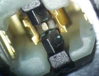
An SEM analysis shows the material to be Copper Oxide with traces in descending order of Aluminum, Silicon, Gold, Chlorine and Calcium.
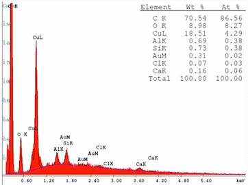
I'm an not at all familiar with electroplating but am thinking that the copper contacts were gold plated with an aluminum barrier metal. Maybe. The potential difference that would have existed across the contact gap was 24 VDC. Could the deposit I'm seeing be the result of electrolysis caused by moisture ingress inside the switch. Why would it be deposited on the insulator though?
Nigel O DuibhgeannáinCEI Ltd. - Meath Ireland
May 9, 2017
publicly reply to Nigel O Duibhgeannáin
A. Hi Nigel
First; no oxides of copper are green
Looking at the SEM scan, the high carbon and oxygen content indicates an organic compound. Pure copper is never found in spring contacts in switches. Beryllium copper alloy is common which explains the silicon. Both Beryllium and aluminium are difficult to detect by SEM and that peak could be either. Aluminium is a non-starter as a barrier layer and the minor elements are typical background contamination so we are left with a green organic copper compound.
I once was presented with a huge mainframe computer with every solder joint green (forty shades) and thousands of them!
My money goes on soldering flux residue.
Shorting by water seems probable and water would remain trapped in a small switch long after it had evaporated on an open circuit board.

Geoff Smith
Hampshire, England
publicly reply to Geoff Smith
Thanks Geoff.
So not copper oxide. What about copper carbonate
⇦ this on
eBay
or
Amazon [affil links]
? I'm not sure about solder flux as there is a distinct track between the opposite polarity contacts. If you look at the second photo you can see where there is a break in the track at the centre contact.
I decided to attempt a rough shod electrolysis myself just to see if my theory was possible. All things not being equal of course - different water used and a different copper alloy used. I sanded the copper to remove the plating that would have been on it. I applied the 24 Vdc. You'll see the photos below. I assume the final colour can vary depending on any other chemical elements that may be present but after drying it out a little bit I was definitely looking at the more greenish hue I saw inside the switch. All this was done in less than 24 hours.
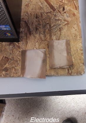
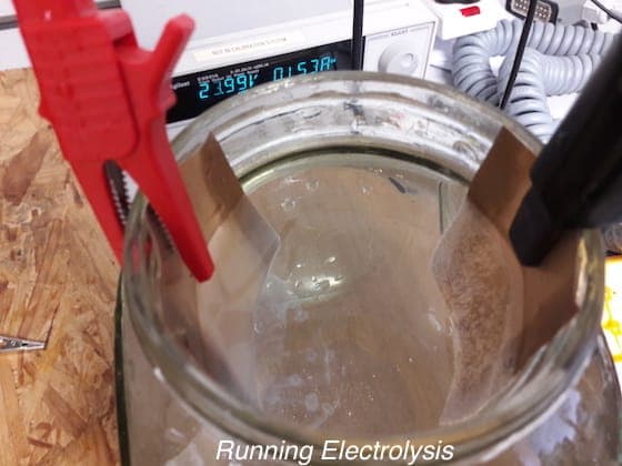
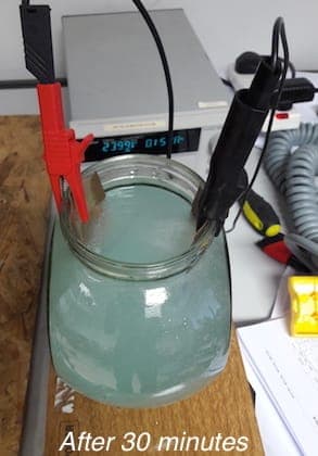
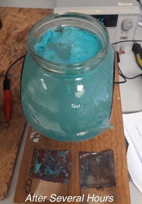
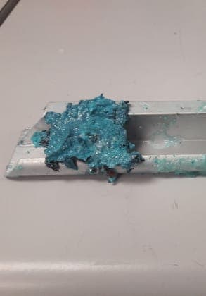
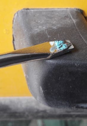
Note: I removed the potential difference first, as would have been the case with the switch. The water would have evaporated over time long after the voltage was removed.
Nigel O Duibhgeannáin [returning]CEI Ltd. - Meath Ireland
publicly reply to Nigel O Duibhgeannáin
A. Hi Nigel
Copper carbonate
⇦ this on
eBay
or
Amazon [affil links]
would not explain the very high sem peak for carbon.
The fluxes used in electronics are either based on colophony resin or in current production organic acids such as lactic, stearic acid
⇦ this on
eBay or
Amazon [affil links] or citric. They work by dissolving oxides of copper and the salts produced are blue / green. The residues are non conductive but are usually removed for aesthetic reasons and to avoid the possibility of future corrosion.
So, though I believe the deposit may be flux residue, I would not expect it to cause a short circuit. Water is much more likely to cause a short but may not be connected with the blue deposit, although some corrosion could be present. However, switch contacts are usually gold plated to avoid corrosion so there could be two unrelated observations.
Two things to try.
Flux residues should dissolve easily in isopropanol.
Check if the short still exists when the switch is completely dry.
One other thought; was this switch specified for 24v at whatever current?

Geoff Smith
Hampshire, England
publicly reply to Geoff Smith
Q. The amount of material I am dealing with is minuscule at this stage. The guy I got to analyse it with the SEM took the majority of it with a swab.
So the little bit that was left I sprayed some Isopropyl alcohol on it. When it dried off the material was still visible in the lumps. If it had dissolved would it have been more evenly spread out?
In terms of the short circuit. That's long gone if it ever existed. I'm looking at this switch which is part of a controller that allegedly failed over a year ago. It is working correctly now, hence I'm speculating that if it did fail it was a short as a result of water ingress that has since dried out but has left behind some residue.
The whole control was specified for 24 Vdc. Of the components that I could read their part numbers, they were rated for 24 Vdc alright. I can only assume the switch was.
Incidentally, I think I can see signs of corrosion inside the switch. If I get a chance I'll try and take a photo. It's quite hard with a microscope and phone camera to get a good shot.
- Meath, Ireland
publicly reply to Nigel O Duibhgeannáin
Q. Hello. I am a scientist making a new device that could benefit from gold plating. Imagine a plate of copper about 1" thick. I will be using high purity copper for its heat conduction properties. I would like to layer it with gold for its chemical inertness. My understanding is that direct plating of Au on Cu is not recommended. Typically an interfacial layer of Ni is deposited on the Cu, then Au is plated on the Ni. Assuming the Ni layer is thin I suspect the heat conduction of the Au/Ni/Cu...Cu/Ni/Au sandwich will not be severely compromised. My Qs are these: how thin a layer of Ni is enough to keep the Au from dissolving in the Cu? And how can I guarantee a flat Au surface on the final device? Thanks for feedback.
George DeTittaJelly Jar Labs - Buffalo New York USA
January 27, 2020
publicly reply to George DeTitta
Q, A, or Comment on THIS thread -or- Start a NEW Thread
