Curated with aloha by
Ted Mooney, P.E. RET

The authoritative public forum
for Metal Finishing 1989-2025

-----
Plating thickness gage R&R Study
Q. Gage R&R for an XRF plating thickness tester - Zinc over steel?
We have been tasked by our IATF 16949 auditor to do a gage R&R for our XRF plating thickness tester. Has anyone here successfully conducted such a study? It seems almost impossible to collect a range of samples of different plating that are across the specification range. It also seems that where the part is tested will impact the test. Any thoughts or guidance?
Dan Watson- Tyrone, Pennsylvania
June 9, 2021
⇩ Related postings, oldest first ⇩
2001
ACRONYMS:
R&R = Repeatability and Reproducability
Q. Looking for a method of measuring high phosphorous electroless nickel thickness of .001-.0013 that will pass a R&R study at 10%-20%. I work for a machining company that has to meet a tight Caterpillar spec.
Tim Nichols- Franklin, Wisconsin
2001
A. Tim:
We have done R&R studies on plating thickness using metallographic cross sections and microscopic measurements. This method is often the referee method for disputes with nondestructive tests. Although we only do metallography, I would think that XRF should also be able to get you good enough data if your parts' geometry is suitable.

Larry Hanke
Minneapolis, Minnesota
A. We use eXacto thin film thickness gauge (which is made by a company called Elektrophysik) to measure the thickness of the electroless nickel plating on the steel. We never did the R&R; study for this gauge anyway. We only compared our test result with the data measured from the micrometer and found they agreed.
Is the unit for the thickness of 0.001 to 0.0013 inch? If yes, I don't think you need to worry about the measurement very much. The processing time to accumulate the thickness for 1 micrometer of high Phosphorous electroless nickel plating is long enough. Thus the thickness of the plating for 0.001" (25 micrometers) to 0.0013" (32.5 micrometers) is easy to control once the processing time is set well. Of course, it would be a very critical specification if it means 0.001 mm to 0.0013 mm.
Charles ChanTaipei, Taiwan
2001
2001
A. We conduct R&R studies using XRF on most finishes on most substrates. We have found this to be an eye opener in respect that the variability found upon the part, and from part to part, makes your target of 10 - 20% virtually impossible to achieve, even with the so called uniformity of electroless Nickel. The degree of accuracy that we've found is ± 9% (ev) add that to your part variation and appraiser variation and your total % R&R is rarely less than 30%.
We overcame this problem by using a piece of pre-plated strip with 10 measurement points 1 inch apart thus reducing the pv value.
Hope this helps.
Seamus Bourkeelectroplating - Birmingham, United Kingdom
Q. How can I make a good R&R study for XRF equipment?
I work in company that manufactures PCBs, and every time I found the total % R&R more than 30%!
- - el azib, Tunisia
April 15, 2018
A. Hello Molka, apparently the standards you are using to calibrate the XRF need to be replaced. 30% differential is way too high.
Mark BakerProcess Engineering - Phoenix, Arizona USA
April 18, 2018
A. Hi. This subject is brand new to me; I just read about it yesterday, but find it interesting.
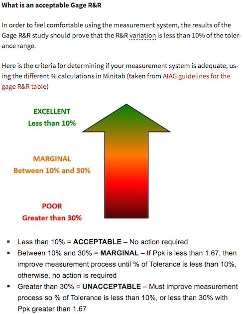
Although the R&R gage study typically involves 2 or 3 operators, 5 to 10 parts, and 2 or 3 measurements of each part by each operator, for simplicity if the thickness was supposed to be 0.001" ± .0001" and the thickness at a given spot was measured by two inspectors as .00100" and .00106" that would be a 'poor' 30% R&R gage error. For an 'excellent' 10% R&R gage score they would have to both measure between .00100" and .00102".
Regards,

Ted Mooney, P.E. RET
Striving to live Aloha
finishing.com - Pine Beach, New Jersey
April 2018
Q, A, or Comment on THIS thread -or- Start a NEW Thread
