-----
Copper Electroplating Experiment with Salt Bridge
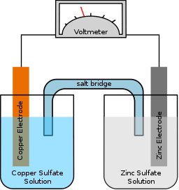
Hope you are having a wonderful day. I have a few questions regarding electroplating. At our school, we did an experiment using zinc and copper metal, and zinc nitrate+ copper sulphate ⇦ on eBay or Amazon [affil link] as the electrolyte. We put the copper metal sheet into a beaker [beakers on eBay or Amazon [affil link] with copper sulphate and the same for zinc. We connected alligator clips onto the plates, and connected the copper one into the negative and the zinc into the positive. We completed the circuit is a sodium chloride salt bridge.
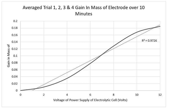
Our independent variable is volts and dependent was mass change of the copper electrode (we are plating copper). This is the graph we got:

My question is why does the copper increase in mass at a slower rate between 0-4volts and then rapidly increase. I understand at higher volts it causes burning, which explains the slow down between 8-12 volts.
Awaiting your response,
Basil TomDarwin, Northern Territory, Australia
September 19, 2019

attribution credit: Gringer [CC BY-SA 3.0 (https://creativecommons.org/licenses/by-sa/3.0)]
A. Hi Basil. I never did that sort of experiment either in school or industry -- in fact I had to look up exactly what a salt bridge is -- so I'm not sure if I can help :-)
But a couple of notes: nitrates are never used in electroplating because of their oxidizing power and the possibility of their reduction; you really should use sulphate. Are you sure the zinc and copper plates sat in solution long enough to be at equilibrium before you made any electrical or salt bridge connections?
It's a bit difficult to relate copper deposition to applied voltage or current flow in a situation like this where it "volunteers" due to it being more noble than the zinc. I think the usual thing to do is hook it up the opposite way, note that there is neither deposition nor dissolution of either plate when the power supply is at 1.16 Volts, and then increase the voltage to make zinc deposit instead of copper and see if the deposition is proportional to the voltage. Actually the deposition will be in direct proportion to the current per Faraday's Law of Electrodeposition, but I'm not sure that the resistance can be counted on to be invariant, and neither therefore can we count on the deposition being exactly proportional to the applied current.
Hopefully a reader well versed in this experiment can be more helpful.
Regards,

Ted Mooney, P.E. RET
Striving to live Aloha
finishing.com - Pine Beach, New Jersey
Ted is available for instant help
or longer-term assistance.
September 29, 2019
A. Hi Basil
An interesting experiment and well recorded.
I cannot offer a complete explanation but a few thoughts.
An ammeter in circuit would give much more useful information.
copper sulphate electrolytes usually contain some sulfuric acid.
Faraday's law is always strictly obeyed but the ions released are not always metal,(actually it is very reliable for acid copper sulphate. This is one reason for not using nitrates which decompose. Did you notice gassing at any of the surfaces?
Depending on the surface you started with, it may become rougher or smoother when plated. This changes the effective surface area.
Chloride in your bridge introduces another unknown. Could it leak into either cell? Was the bridge big enough to carry the current? A sulphate bridge would be better at reducing the variables.

Geoff Smith
Hampshire, England
Q, A, or Comment on THIS thread -or- Start a NEW Thread