Curated with aloha by
Ted Mooney, P.E. RET

The authoritative public forum
for Metal Finishing 1989-2025

-----
Amperage measurements for copper plating bath do not make sense
September 22, 2017
Q. I am trouble shooting plating problems with our copper plating bath.
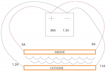
We are setting our rectifier to 36 amps at 1.2 volts. The cables from the rectifier to the tank are approx. 20 feet long. We have two cables coming off the positive side to each end of the anode plating bar and two off the negative side to each end of the cathode plating bar.

I am measuring amps with a clamp meter through the cable, near the connections to the plating bars, and there is a significant drop.
I am getting 5A on one end of the anode bar and 9A at the other end.
I am getting 1.2A on one end of the cathode and 11A at the other end.
I have tried multiple clamp meters with the same results.
Here is my question, should I expect to see the same amperage at each end of the same bar? Is this drop caused by the resistance in the cables?
I suspect there is corrosion in the cables causing the issue. Not sure of the efficiency of a copper plating bath. What would be normal amps readings at the connections near the plating bars. Thanks in advance for all of your help!
Process Engineer - San Marcos, California, USA
QUICKSTART:
How a rectifier ammeter works --
A rectifier has a "shunt" in its bus bar near where the bus exists the case. A shunt is a block of copper of precise formulation and dimensions such that it has a very exact resistance. The resistance of most shunts is chosen such that the voltage drop across them will be 50 millivolts when the rectifier is operating at full rated amperage.
For example, the voltage drop across the shunt of a 100 Amp rectifier will be 50 mV when it is putting out its full 100 Amp power rating. Wires are attached from the two ends of the shunt to the ammeter. So the "ammeter" is actually just a 0-50 mV voltmeter, with the scale on the front of the ammeter reading 0-100 A instead of millivolts.
If the shunt has other than a 50 mV drop at full amperage, or a replacement meter is installed which is not a 0-50 mV one, or it is of a different scale, e.g., 0-50 A or 0 -200 A, the readings will be wrong.
Hi Eric. I don't think I'd be concerned about the variation in current measured at the two ends of the bars. I suspect that the cables to your anode & cathode rods are generously sized, such that the resistance in the cabling is minimal and the current is primarily taking the path of least resistance even though the difference in resistance may be close to zero. The total reading between both ends is all that I'd worry about.
But I do see an anomaly here in that your rectifier gauge claims 36 amps, whereas your multiple clamp meters read about 14 amps to the anodes and 12 to the cathodes instead of 36 to each. This may be a result of clamp meters designed for much higher amperage being unable to discern smaller amperages with accuracy, or the meter on your rectifier might be wrong if the rectifier is old and the meter has been replaced.
What is the plating problem that you are experiencing? Maybe people can tell you whether they think that sort of problem is likely related to electrical issues or not.
Regards,

Ted Mooney, P.E. RET
Striving to live Aloha
finishing.com - Pine Beach, New Jersey
September 2017
![]() Thanks Ted for the information. We found the cables were in various stages of corrosion. Once we cut back to clean copper and reattached the cables, the amperage meter readings matched the rectifier readings.
Thanks Ted for the information. We found the cables were in various stages of corrosion. Once we cut back to clean copper and reattached the cables, the amperage meter readings matched the rectifier readings.
- San Marcos, California, USA
September 26, 2017
Q, A, or Comment on THIS thread -or- Start a NEW Thread