-----
Exhaust method & calculations for plating tanks
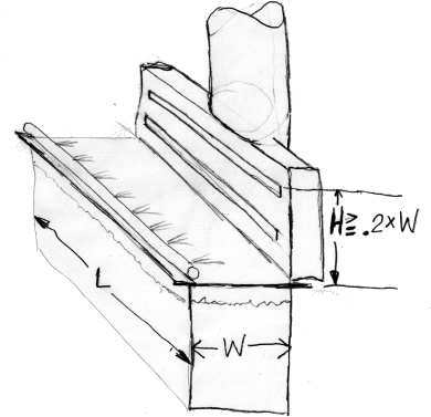
Most heated plating tanks and some unheated chemical process tanks in a plating line require exhaust ventilation systems to remove the mists and fumes. The most common approach is to mount PVC draft plenums along the edges of the long sides of the tank, or to put such a system on one side of the tank and a push-air system, per the illustration below, on the other side of the tank.
Q. Hi Ted, I am Juan Portillo and I have been read the Industrial Ventilation book. I am studying the example about the chrome plating tank hood design which comes in the caption. But I have a doubt about the plenum depth size and how you apply this in the hood design. Could you help me to understand it please.
Thank you
Best regards,
Maintenance Manager - Toluca Mexico
November 17, 2024
A. Hello Juan,
I don't want to add confusion by misunderstanding what you mean by plenum depth but the exhaust hood I illustrated has a height dimension, but does not have any other dimensions. By 'depth' I think you mean the dimension of the hood/plenum in the other direction, 'left to right on your computer screen' ?
When designing a slot, plenum, and duct pipe system, you'll have some number of CFM you want to exhaust. And the slot velocity, the plenum velocity, and the duct velocity would be that CFM divided by the area of the slots, the plenum, or the duct pipe. Actually. if the duct pipe is in the middle of the exhaust hood/plenum, the plenum velocity would be half that, because half of the exhaust air is running towards the center from each end.
If I recall properly I usually used 3000 FPM as the slot velocity, 1500-2000 FPM as the plenum velocity, and 2500 FPM as the duct pipe velocity. Different designers might use different numbers, usually higher these days, but their relationship should be preserved. That is, the slot velocity should be higher than the duct velocity, and the plenum velocity should be much lower, and this is why:
You want the exhaust air to come in along the whole length of the slots, so you keep the slots small so all of the air can't lazily come in from just one area but must be distributed along the full length of the tank. You keep the plenum velocity low so there is very little resistance in the plenum, so the slots rather than the plenum control the distribution.
The area of the plenum should be CFM ÷ Area; or in the case of the duct being in the middle of the plenum, CFM ÷ 2 ÷ Area. And the area of the plenum is the height X 'depth'.
Luck & Regards,

Ted Mooney, P.E. RET
Striving to live Aloha
finishing.com - Pine Beach, New Jersey
Ted is available for instant help
or longer-term assistance.
⇩ Related postings, oldest first ⇩
Q. Dear Mr. Ted
Can you help me please to get information on how to calculate a lip tank air extraction volume (cfm/sq. feet) for hot alkaline cleaning tanks.

Khair Shishani
aircraft maintenance - Al Ain, UAE
August 26, 2015
A. Hi Khair. It's nice to have you visiting the site again; your postings have been a big help to many people.
Years ago I designed numerous exhaust systems for plating lines, but I haven't done so for a while and my memory is fading. If you can find a copy in a library, "Industrial Ventilation" by the American Society of Governmental Industrial Hygienists is an excellent reference work on the subject.
Generally, ventilation rates of 150-250 CFM per square foot of tank surface (L x W) are appropriate for hot alkaline cleaning tanks. However, if the geometry and ergonomics are favorable, such that a high pressure / low volume push-pull system is reasonable, these figures can probably be cut approximately in half.
Some of those factors would be that:
- the tank is longer than it is wide, so a ventilation hood can run the long direction, and the movement of air is across the short side.
- a push-pipe can be fitted along the other long side.
- the hoods can be tall enough to capture the fumes pushed across the tank (as I recall, 20% of the exhausted width).

If you cannot apply push-air though, dimensions start becoming critical and spans greater than 36" are a problem even with lip-type exhaust hoods on both sides of the tank (reason: it's easy to blow out a candle, but almost impossible to extinguish one by inhaling; pushed air has momentum & direction so you can send it where you want, but when you have only suction, air will rush in from every direction not just from where you'd like it to come).
Regards,

Ted Mooney, P.E. RET
Striving to live Aloha
finishing.com - Pine Beach, New Jersey
Ted is available for instant help
or longer-term assistance.
![]() Dear Mr. Ted,
Dear Mr. Ted,
thank you and the best for you and family, thanks again .

Khair Shishani
aircraft maintenance - Al Ain, UAE
Push manifold for open surface tanks (plating shop)
Q. Is there a way to lock in place the push manifold for a ventilated open surface tank. Shop currently using a general purpose dial with no settings.
If dial is turned up too high, the push air stream overwhelms the slot hood exhaust. Too low would not work either.
A smoke/fog generator used to visualize.
- San Diego California
November 5, 2020
A. Hi Catherine. If I recall correctly, "Industrial Ventilation"
by ACGIH
⇦[this on
eBay,
Amazon, or
AbeBooks affil links]
talks about two different types of push-air approaches, high volume-low pressure and low volume-high pressure (although 'high pressure' is still less than a psi).
It sounds like you are describing the high volume-low pressure approach. My own experience, although it included designing dozens of push-pull ventilation systems, was limited to the low volume - high pressure approach, which included no dials or settings -- just small holes on 1" centers drilled into a 1-1/2 or 2" PVC pipe per the illustration above.
I never saw one that didn't work exceptionally well except as long as an obstruction didn't block the path of the push air. It's hard to imagine this low volume approach 'overwhelming' the hood exhaust regardless of settings.
If I recall the manual correctly, the high volume approach was usually done with a slotted pipe, maybe with the slot held to dimension with screw-type pipe clamps or with a slot in a small box? I never designed one, never had full faith in them, and couldn't understand the point since the other approach worked so well (although I don't insist that the design I used is better than the other, just that it's very good).
Please briefly describe your system: How wide are the tanks? What is the push air pressure? What is the air volume per square foot or per lineal foot? What does the push air manifold look like? Thanks!
Luck & Regards,

Ted Mooney, P.E. RET
Striving to live Aloha
finishing.com - Pine Beach, New Jersey
Ted is available for instant help
or longer-term assistance.
Q, A, or Comment on THIS thread -or- Start a NEW Thread
