-----
Agitation air sizing and calculations for plating & anodizing
Q. HELLO.
I'M A PROCESS ENGINEER IN THE PCB INDUSTRY. I WOULD LIKE TO GET SOME INFORMATION ON AIR CONSUMPTION IN THE ACID COPPER ELECTROPLATING PROCESS.
THANK YOU IN ADVANCE.
2001
A. I'm not sure what you mean by air "consumption". You do not "consume" air in acid copper plating, you are using air from a blower to agitate the bath (you are trying to rapidly replenish the copper concentration in the work/liquid boundary layer). As a rule of thumb, you would want to raise the solution layer about 3 cm (1") if you are looking for how much air you need.
There are also issues about sparger design and placement; you should consult with your supplier.

James Totter, CEF
- Tallahassee, Florida
A. If your question is about how to size the blower, you need 1 pound/square inch/ 18 inches of solution depth, and 1 cubic foot/minute/linear foot of perforated pipe.
Perforated pipe: 3/32" diameter holes, spaced 3.75" apart. pipe diameter determined from cross sectional area of all drilled holes in the pipe. (3/4" schedule 80, .154" wall), this works out to no more than 10 feet long from the header.
Your supplier should be able to size the blower and pipes for you.

Tom Pullizzi
Falls Township, Pennsylvania
Multiple threads merged: please forgive chronology errors and repetition 🙂
Design of a blower system for air sparging
Q. In a blower sparging system, what should the relationship be between the area of the discharge pipe from the blower and the total area from all of the sparger holes in the tanks? My gut tells me that the area from all of the holes should be less than the area from the blower to ensure that all of the holes discharge air; but how much less? I think that if it is very much less, we may be adding too much pressure for the blower to handle. If I am on the right track, is there any way to calculate the increased pressure at the blower due to that restriction?

Jon Barrows, MSF, EHSSC
Kansas City
2005
A. Hi Jon,
You worry too much, methinks.
Have a gander at thread #9311, 7718 and #8345 .... they might give some insight, then again they might not!
You are right to assume that the area should be less than the blower outlet size ... one needs distribution even to the farthest hole.
If you are really worried, then test the motor output to ensure you are not overloading it.
I seem to remember that the farthest hole was a smidgen LARGER than the others to ensure that one achieved the right distribution. Most holes being, say, 1/8" and spaced at 6" to 12" apart.

Freeman Newton [dec.]
R.I.P. old friend (It is our sad duty to
advise that Freeman passed away 4/21/12)
![]() You're probably right, I'm sure the system is a little more flexible than I have implied. I just want to get it right the first time if I can help it. Anyway, I think I found the missing piece that I needed in a technical bulletin from a regenerative blower company. It turns out that you want 1.0 in2 of total open hole area for each 62.5 SCFM in the system. That along with Ted's article in the Guidebook, gave me everything I needed to size the blower and agitation lines properly. Thanks.
You're probably right, I'm sure the system is a little more flexible than I have implied. I just want to get it right the first time if I can help it. Anyway, I think I found the missing piece that I needed in a technical bulletin from a regenerative blower company. It turns out that you want 1.0 in2 of total open hole area for each 62.5 SCFM in the system. That along with Ted's article in the Guidebook, gave me everything I needed to size the blower and agitation lines properly. Thanks.

Jon Barrows, MSF, EHSSC
Kansas City
A. Hi once again, Jon
Have a gander at thread #7794, The Court Industries application.
Yes, I know that this was for air ... it's just that water is a heavier medium, that's all.
The crux is to place a larger hole at the very end of the pipe to aid distribution ... but your 62-1/2 CFM is insignificant, I feel ... what matters is the PRESSURE your pump generates.
Something else, before I forget ... if you are using plastics, i.e., PVC pipe spargers, DON'T use an ultra small hole. Why? Because the drill bit will gum up and partially close those holes if, say, you use 1/16" dia.

Freeman Newton [dec.]
R.I.P. old friend (It is our sad duty to
advise that Freeman passed away 4/21/12)
Multiple threads merged: please forgive chronology errors and repetition 🙂
Q. I want to properly size the compressed air supply for agitation in copper electrowinning tanks. I am stuck on how to calculate the required CFM flow required. Tank size is 6.6m long x 1.4m wide x 1.2m deep. I have 86 cells.
Stephen MurefuRio Tinto Zimbabwe - Harare, Zimbabwe
2006
A. A fairly common air agitation sizing is 5 ^0.5 CFM per square foot of tank surface area (recalculate for metric). Use a throttling valve for adjustment and make sure your air supply is clean. High pressure blowers are commonly used in lieu of compressed air.
- Hickory, North Carolina USA
Ed. note: We're quite sure that Rick's posting was missing a decimal point before the 5.
A. Hi Stephen,
This data won't help you determine the airflows BUT it sure could be, I think, of some assistance in getting a good distribution of the air along your longish tanks.
Please go to the archives and hit letter no. 7718 and # 9311.

Freeman Newton [dec.]
R.I.P. old friend (It is our sad duty to
advise that Freeman passed away 4/21/12)
A. Hi Stephen,
The volume of air required will be determined by three factors-
1. Depth of the tank will determine the pressure needed to ensure that the liquid does not enter the air line.
2. Diameter of the hole through which the air is to escape.
3. Number of holes in the piping.
Area of hole multiplied by number will give you the effective orifice size.
Head pressure (in Pascals ) "p"= d x g x h (d=fluid density approx. 1000kg/m3 for water, g= gravitational force approx. 9.8, h= tank depth in meters)
> From a table you should be able to find the flow through the effective orifice at the calculated pressure.
I would suggest that the supply air be filtered and dried at the highest possible pressure to ensure that there is no contamination(oil water emulsions/ dirt) introduced into the tanks and there after reduce the pressure and add a flow control valve and non return valve just to be safe.
If I can assist further please let me know.
Regards,
- Cape Town South Africa
Q. The topic is currently going on as one of my design job. I want to know the calculating amount of air required to agitate the tank mass and its pressure. The topic of sizing is still unclear; I am not understanding how to calculate amount of air required for agitation.
Anand S. Karmarkar- Pune, India
June 25, 2009
A. Hi, Anand. To set the stage, we are talking about plating and metal finishing tanks here. It isn't clear what your topic is, but if it's not metal finishing, then this has no validity.
Rick Hall gave a figure of .5 CFM per square foot of tank surface. That means you multiply the width of the tank by its length, express that in square feet, and multiple by 0.5.
This is, of course, just one designer's approach. Others say use 1.0 CFM per linear foot of air agitation piping. Some tanks, like rinse tanks, might have one row of pipe from one corner of a tank to the diagonal corner. Other tanks like nickel plating tanks would probably have a row between each anode and cathode bar.
You need sufficient pressure to push the air down against the hydrostatic pressure of the solution in the tank, plus some more for dynamic losses. Some designers say that a good number is one ounce of pressure per inch of solution depth.
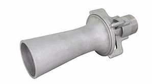
You might also consider that many new installations are moving from air agitation towards eductors. This is a system where venturi style eductors are put into the pipe, instead of holes, and the pipe is connected to a recirculating pump instead of an air supply. Good luck.
Regards,

Ted Mooney, P.E.
Striving to live Aloha
finishing.com - Pine Beach, New Jersey
Ted can be retained for immediate
answers or long term project help
Air agitation energy consumption/costs
Q. Does anyone know how to calculate the cost of compressed air used in air agitation of plating and degreasing tanks. If we have a compressed air system operating at 100 psig and an air agitation pipe at the bottom of a plating tank containing 19 holes, each being 1/4 inch diameter, how much air (CFM) will flow through each hole?
S Podgorickplating shop employee - London, UK
March 24, 2010
|
A. Are you sure you want to use compressed air? Unless you've taken extraordinary precautions, there is a real possibility of blowing oil from the compressor into your plating tanks.  James Totter, CEF - Tallahassee, Florida A. Sir: Galvanizing Consultant - Hot Springs, SD 57747 A. There are other factors to consider in the exact costs involved here. Size of the supply line, length of the supply line, any reductions in the air supply line, air leaks if any, temperature, multiple process ports (split-offs), specific gravity of the solution(s)(resistance). I can give you the basic electrical usage calculation though. fellow plater - Syracuse, New York USA |
A. It is off point a little bit, but a useful rule of thumb to consider is that air compressors will deliver only about 4 cfm per horsepower whereas properly sized low pressure blowers deliver about 28 cfm or more per horsepower. In dollars per year these differences are amazing. Please don't consider using a 100 psi air compressor to agitate tanks that only require 3-4 psi of air pressure. Instead invest in a low-pressure blower which will pay for itself very quickly.
Another rule of thumb for air agitation is that mild agitation is considered to be around 0.5 cfm per square foot of tank surface area and vigorous (such as for hard anodizing) is going to be around 1.5 cfm per square foot of tank surface area. 0.5 cfm/ft2 is plenty for most purposes and anything above that is is probably wasteful. Your hole sizing is probably not optimized for the air agitation that you need. If you have a Metal Finishing Guidebook, then you should definitely read Ted Mooney's article entitled "Solution Agitation and Mixing". It is excellent.

Jon Barrows, MSF, EHSSC
Kansas City
Q. Whist I understand the need for air as a method of agitation I am constantly told by chemical suppliers that in certain acid coppers, whether for PCB or for other forms of plating, that air is essential in order to 'activate the additives'. The question that I would have is how much of the air is for activating additives and how much for agitation?
Robert Sawyerilter company - Manchester, United Kingdom
June 1, 2011
Air agitation blower problems
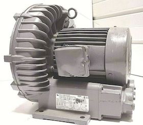
Q. Has anyone installed a filter between a HOFFMAN air agitation blower and plating line? We have 2 micron filtration on the inlet to the blower but would like to find a post filter system for the unit.
Brian StoiberTechnical advisor - New Berlin, Wisconsin USA
Hoffman Blowers and Parts on eBay (affil link)
Q. In low pressure air agitation, approximately how many or how much CFM and PSI of free air am I going to supply at a 30 lbs can?
Thank you in advance!
- Quezon City, Philippines
April 11, 2016
? Hi Ricyl. Sorry, I cannot decipher "30 lbs can"; please try to re-word it for me. And what kind of electroplating are you doing?
Regards,

Ted Mooney, P.E. RET
Striving to live Aloha
finishing.com - Pine Beach, New Jersey
Ted can be retained for immediate
answers or long term project help
A. Good day Ricyl.
Try a search for GAST BLOWERS. It will give you details on air sparger requirements.
Regards,
- TorOnto Ont Canada
Gast Blowers and Parts on eBay (affil link)
Q. How much CFM air agitation is required for hard anodizing process of aluminium? Our tank size is width-1.5m, length-4m and depth-2m. We are running total 5 tanks of this size by one compressor. So how much capacity is required for compressor?
Prakash ChaudharyVadodara, Gujarat, India
March 19, 2019
Treatment &
Finishing of
Aluminium and
Its Alloys"
by Wernick, Pinner
& Sheasby

on eBay or Amazon
or AbeBooks
(affil link)
A. Hi Prakash. Wernick, Pinner & Sheasby references T. Turner's Aluminum Association Finishing Seminar 1968 mention of 0.22 - 0.45 m3 of air per m2 of tank surface for decorative anodizing. Certainly the high end of this would be appropriate for hard anodizing. 0.45 m3/m2 of surface is very close to Jon's 1.5 CFM/ft2.
Be careful of the word "compressor" though. High pressure blowers rather than general air compressors should be used for air agitation.
And remember that the reason for using air agitation in hard anodizing is a bit different than the reason for using it in electroplating! In electroplating, its roles include general solution equilibrium and stripping small hydrogen bubbles off the surfaces of the work; but its main function in hard anodizing is to make sure the temperature of the parts does not rise; this requires more air discharge holes, and below each piece, not just anywhere.
Regards,

Ted Mooney, P.E. RET
Striving to live Aloha
finishing.com - Pine Beach, New Jersey
Ted can be retained for immediate
answers or long term project help
Q. I just improved my electroforming setup and added much needed agitation. Currently I am using a water pump and I stuffed the end of the hoses, and punctured some holes to make some kind of an air wall. I thought it would agitate the solution more evenly. My problem is: water pump pumps too much air even on the lowest setting and that causes the solution to make bubbles and splatter around. First problem was my copper bar which I suspend my pieces got covered with copper sulphate crystals and it needed constant cleaning. Then I started using a bigger container and filled it halfway and put the bar on top so it wouldn't get covered with acid. It worked but I didn't realize the copper wires that I suspend the pieces were getting covered with acid heavily too, especially the first 1-3 cm. How can I prevent that? I thought maybe if I make my tanks even bigger , it would prevent the bubbles to pop so strong cause they would come from a longer distance but I really don't want to use bigger containers because of the cost and the plating speed. Has anyone encountered this type of problem? Thanks.
Cagin UcarChitta Studio - Turkey Canakkale
May 9, 2019
A. Hi Cagin. We readers have no idea yet how big your tank is, or how deep it is, or how large the "water pump" is, or what kind of pump it is, or how big the hose is, or even what metal you are electroforming with :-)
But it sounds like you have a grossly oversized air pump. The way air agitation is supposed to work is the air bubbles simply rise through the solution because air is lighter than the solution. Consequently, a deeper tank does not absorb their energy and slow them down. In your case it sounds like the volume is so great that you are literally spraying air out of your hose rather than just allowing it to gently float up.
I think the right answer is not to try to fix everything else to match your greatly oversized pump, but to use a more practical agitation system:
- You could recirculate the electroforming solution through that pump instead of using it to pump air.
- You could use a simple mechanical agitation system instead of air agitation.
- You could (perhaps, depending on the type of pump) use a valve or smaller diameter tubing to lessen the air volume -- or at least try drilling larger holes in the hose so gravity propels the bubbles rather than pump pressure spraying it.
Good luck
Regards,

Ted Mooney, P.E. RET
Striving to live Aloha
finishing.com - Pine Beach, New Jersey
Ted can be retained for immediate
answers or long term project help
Q. Hi Ted. I didn't cover a lot of important information did I:)
First of all the pump I am talking about is a 10 watt aquarium air pump and the hose is a little less then 1 cm in diameter, I would check it but I am not at home. Right now the containers I am using are 3.5 gallons and about 11 inches deep, I have 3 of them. Also I am electroforming copper. I was having very heavy dendrite problem especially at the bottom of my pieces and agitation solved it. I will try bigger holes as you suggested and will get back to you. And also I am thinking about maybe I can use a simple "T" shaped plastic separator so less air will go through each hose. Thank you for your response.
Chitta Studio - Turkey Canakkale
A. Hi. It does sound to me like you could put a tee in the hose and bleed off some of the air :-)
Regards,

Ted Mooney, P.E. RET
Striving to live Aloha
finishing.com - Pine Beach, New Jersey
Ted can be retained for immediate
answers or long term project help
Q, A, or Comment on THIS thread -or- Start a NEW Thread

