-----
Ni & SnPb Plating of Surface Mount Chip Resistors
Q. Dear Sir,
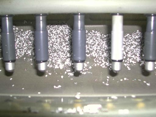
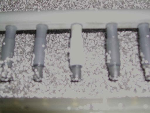
We are a chip resistor manufacturer and we plate nickel (3-5 µm thickness) to our products. We are using barrel electroplating. Recently we have our product burnt in the plating tank. Our product and the barrel electrode head become black like carbon. All the metals (silver and thin layer of nickel/chromium) on our product were disappear. This problem is very random and it happens about 1-2 times a month. Please advise, and I am looking forward for your valuable reply.

(see larger pics below)
Thank you
Best regards
SH Er
- Singapore
2002
A. Er Song,
Your inquiry lacks a lot of detail. Is your operation a manual line or automatic line? Does the bad work happen at the same location every time? Assuming the nickel bath is OK, I will start checking for a stopped barrel, bad power supply, current to the barrel, dirty barrels that do not allow solution transfer, and barrel danglers that are not riding with the load. All these can occur intermittently. Also, check to see if the parts are not over etched before the going into the nickel bath. This will have the same results that you are seeing by removing all the NiChrome.
Good Luck!
- Lebanon, Kentucky
Q. Dear Sir,
We are using a fully automatic line. The bad work happen at the same location (electrode head) in the barrel but can happen in different plating baths and different barrels. There is no barrel stop problem and the power supply is OK. We are seeing a spike or overshooting of current for the initial few milliseconds to the bath. The barrel mesh are clean and the barrel danglers are OK. We pretreat the parts in the 5% sulfuric acid for 1 minutes and follow by about 40 °C of hot D.I water rinsing. We are controlling the baths temperature at 52 degree C and the PH at 3.8-4.2. Please advise and we are looking forward for you valuable reply.
Thank YOU.
Best Regards,
SH Er
- Singapore
A. Ok, I will again check for the following:
a. See if someone is putting the system in hold at any point in time.
b. Check for a stopped barrel. Some automatic systems have an event log and barrel rotation monitoring. The event log can give you a lot of clues. Your problem could be combination of a specific barrel in a specific location.
c. Check your wiring. The plating line environment is tough on copper wire and connections. Is your plating barrels connected to an individual power supply, or is two barrels connected to one power supply?
d. Is the volume of parts and media correct in the barrel?
e. Check to be sure the danglers are riding with the work. What kind of danglers are you using?
f. Check to see if your plating parameters are correct in your computer system. I myself be the victim of someone changing parameters on me.
Intermittent problems are tough to solve. You have to be there when it happens to get that final clue.
Good Luck again.
- Lebanon, Kentucky
Q. Dear Sir,
a. The system is running O.K.
b. Not barrels stop was detected.
c. Wiring should be O.K. We are connected one barrel to one power supply.
d. The volume of parts and the media radio are following our procedures.
e. We are using V-block and the barrel rod sit on the V-block.
f. The parameters are correct base on procedures.
We are there when the burnt problem happened and we do not found any problems. Please highlight to us what are the parameters that will cause burnt products. Because we felt that it should be some parameters having problems and it will happen when the conditions get to the max. or min.limit. Thank you and we are looking forward for you valuable reply.
Best Regards,
SH Er
- Singapore
A. Er Song,
E-mail photo of the defective parts will be helpful. Maybe some cross section photos. OK here is a few more things to check:
1. Resistor plate differently depending on value. The lower the value; the faster the plating rate. Does problem affect one specific part? Try lowering the plating current for that part.
2. Bath metals and pH concentration can affect burning. Increase the metals concentration will reduce burning. Higher pH will reduce burning. Check your plating solution in a hull test.
3. Check your plating media. If you plating media is too large, that will cause problems such poor contact between the parts and media. Large media size has lower surface area for given volume.
4.Check your power supplies again for AC ripple. An oscilloscope is needed to do this. A good power supply should have less than 5% ripple at full power.
5. Check to see if your parts are mixing in the barrel and our not floating on top. Your precleaning process should be capable of wetting the parts well.
Good luck again. I hope this is helpful.
- Lebanon, Kentucky
A. Dear Sir:
1. Check your metal concentration to ensure your bath is at optimum levels.
2. Check your Nickel Chloride concentration and ensure it is at optimum level.
3. Analyze your nickel bath for contamination.
Best Regards,
- McAllen, Texas
Q. Dear Sir,
I am still waiting for the problem to happen and I will E-mail the photo of the defective to you.
1. The problem occur to all sizes, values.
2. We have raise the metals concentration and the pH to the max. of the spec. The Hull Cell
⇦ huh?
test was OK. Please advise the recommended metals concentration and pH levels.
3. We are using steel shot/ball as our plating media and the burnt problem started from the steel shot.
4. We are controlling the current(Amp) for plating and the current are less than 1% ripple. But the voltage have a big ripple of about 10-15%. please advise whether is normal and how to control.
5. All the parts are not floating.
The nickel and nickel chloride contains are within our spec. We do not know how to check for contamination. Please advise how to check for contamination. The only way we checking are by hull cell test. Thank you for the valuable reply and I am looking forward to hear from you.
Thank you
Regards,
SH Er
- Singapore
A. ER Song,
I like to run my nickel metal concentration 14 to 15 oz/gal, nickel chloride 12 to 13 oz/gal, pH 3.5 to 3.8 and boric acid saturated (+7 oz/gal). If you increase the metals, you maybe able lower your plating current which may reduce your chances of burning. I don't think you problem is bath contamination. You will have problem across the board if that was true. However, you can check for bath contamination several ways. First, you can do a hull cell analysis comparing a new bath to your current production bath, or you send your bath to an outside lab for analysis. Metals that I would check for is Fe, Cr, Cu, Pb, and Ag. Your ripple on your power supplies appears to be good.
Let me know what happens.
- Lebanon, Kentucky
A. This sounds like a rectification problem to me. If you are using switching power supplies, I recommend using the crossover mode where you limit both the voltage and the current. This mode of operation will prevent large voltage spikes as the barrel is immersed in the solution. an initial high current spike can passivate the media or danglers and cause the problems you occasionally see.
To use crossover mode set the voltage to the maximum that you observe during the plating process and then set the current to the desired value.
By limiting the voltage you can not get a large current spike.
Good luck,

Pat Mentone
St Paul, Minnesota
A. Dear SH Er,
I work in the plating shop of a ceramic capacitors manufacturing company, and we have seen the same problem as you randomly. Some times we have fixed the problem by dummy plating and purifying the solution. To purify pump out the solution to an auxiliary tank and add 0.4 oz/gal of carbon activated with agitation for a few minutes, then add Nickel Carbonate to raise the pH to 5.2, then add 1 ml/L of Hydrogen peroxide (30%) and maintain warm the solution for 2 hrs. Finally filter the solution and pump it back into the plating tank. On top of that try an electrolytic purification by dummy plating a
12" x 12" corrugated steel plate for 2 hrs at 2 amps.
Good luck.
Questions: What kind of anodes are you using? Is the anode/cathode ratio close to 2/1? What about the anode/cathode distance?
- Valencia, California
Q. Dear Sir,
Thank you for your valuable reply.
By increasing the nickel and nickel chloride concentration will increase the pH to 4.5. We try to lower the pH by adding the Boric acid. But look like the pH only reduce 0.1-0.3 only. And after 1-2 days of plating. The pH will raised to 4.5-4.7 again. Please advise
... We are using PC connected to rectifier and the PC will adjust/maintain the current by increase or reduce the voltage. We are not sure how to use the crossover mode.Please advise.. We are using INCO R-round/crown anodes and the anodes are about 10 inches away from the Cathode. Please advise how to check for the anode/cathode ratio.
Thank you and we are looking forward to hear from you.
Best Regards,
SH Er
- Singapore
A. Boric acid is a buffer, not a true acid, it will work to maintain the pH at 4, but it is of limited capability. You need to be adding whatever acid your original makeup called for, i.e., sulfamic acid
⇦ on
eBay
or
Amazon [affil link] for sulfamate and sulfuric for sulphate nickel and hydrochloric for chloride nickel and on and on.
If your firm does not know these very basics, they need to buy some books on plating or hire a consultant.If you are using proprietary chemicals, then the vendor should be helping you on the chemistry aspects.
- Navarre, Florida
A. I think that you use a sulfamate nickel solution and not a sulphate one. Do you use any additive in this solution? I would try to increase the addition agent (not the anti pitting) as lack of it can increase burning. One more thing - in case you have chromium plus 6 impurity in the solution (even a few ppm) it will burn. It is very easy to check chromium existence in a nickel solution by diphenyl carbazide indicator.

Sara Michaeli
Tel-Aviv-Yafo, Israel
A. ER Song,
Are you still having problems? You can lower your pH by adding sulfamic acid. Your anode/cathode ratio is the surface area of the anode basket facing the barrel (times two)compare to all the plateable surface area in the barrel. Note,this can be miss leading. Not all the material in the barrel is under power at the same time, so your current density in a barrel is much higher than you realize. Your barrel should contain no more than 30% to 40% full of material. I prefer loading a barrel no more than 35% maximum volume with a mixture of parts to media of 1 to 2-3.
Sorry, can't help with the power supply.
- Lebanon, Kentucky
A. Hi Guys,
You all are trying to look into the chemistry of the bath and trying to get a solution. This not a problem with the bath.
The bath will not go bad suddenly for one lot (one barrel) and for the next barrel it will not become alright. The problem lies in the components. Actually chip resistors are plated along with steel shots
(media). This acts as a conductive media as well as provides tumbling action so that the small components don't stick to each other during plating.
The reasons for the failure are,
1. Improper Media size and components. Sometimes the media become larger in size and will not provide enough distribution of current. The trick lies in how often the media comes in contact with the component. The symptoms are longer duration of plating and low thickness.
2. Another problem lies in the Front end of the Thick film resistor making operation. Actually a Silver conductor paste is used as the electrode. The Silver is bonded with the ceramic surface with binders made of glass. So the distribution of Silver in the electrode plays a vital role. If the silver distribution is not good the problem will be caused. So during the printing operation is should be made sure that the viscosity of the Silver paste is maintained properly. This pertains to the F.end operation of resistor making.
3. If they are using a Polymer conductivity paste instead of Glass paste, they have to take a look into the expire date of the polymer or the quality of the paste. This can provide a vital clue.
4. The most important thing is the dangler(electrode) used in the barrel plating. The dangler thickness grows every time when it is plated. If the dangler becomes over size and half the portion is immersed and half not immersed during the plating. There will be surge of current flowing thru the dangler sharp regions and the blacking in of dangler as well as the resistors can happen. The dangler has to ground properly and the edges closed with a heat sink tape so that the dangler doesn't grow abnormally.
5. Dangler not immersing properly. Often the dangler goes upwards without giving contact to the media or components this also can give the same blackening problem. He should ensure that the dangler is immersed properly every time and all time. This has nothing to do with the chemistry of the bath. If the chemistry is bad the plating won't be good and there will not be enough nickel to provide a barrier layer and this can be easily identified with the solder leach test which is performed after plating. This is not a plating problem alone it also have some thing to do with Thick film manufacturing process also. Apart from this you have to stick to the basics of plating. Keep the basic parameters perfect and start your troubleshooting.
You need not wait for the problem to happen. You can simulate the same condition but bending the electrode, plating with waste components .. etc. Hope the detail I provide should be sufficient to solve your problem.
Good luck ..
- Singapore
Q. Dear Sir,
Thank you very much for all your valuable answers. First, I want to answer Ms. Sara, We are using slotanik BFL additive and slotanik M additive. We use Boric acid as a buffer and sulfuric acid to lower the pH. After monitoring the plating condition for few months, we have more burnt problem after pouring sulfuric acid to the plating bath. I am not sure whether the problem with the sulfuric or coincidence. We don't have Chromium+6 in the bath.. Attached are the burnt photo compare with good barrel in the plating line.


SH Er
Er Song Hwee [returning]- Singapore
A. Hi Song,
Did you manage to solve your problem. If you still believe the chemistry has problem try this,
Since you are plating the Chips components I believe you will be using low CD (.25 to 2 asd) it is better you do a hull cell at .25 Amps for 20- 30 mins to get a clear picture of the bath behavior in LCD area. Ensure that all the area in the hull cell have a good coverage and check for brittleness in HCD (brittleness at HCD can be caused by organic contamination). If the coverage is good through out the panel there is nothing wrong with the chemistry. Coming to the addition of sulfuric acid to lower the pH. DO you add concentrated acid to bath? If so. stop the practice immediately. It's always recommended that sulfuric acid [sulfuric acid on
Amazon, affil link]
should be properly diluted when you add to reduce the pH. If you add concentrated acid, the brightener system may decompose and cause organic contamination to the bath. Then the only way to remove is Activated carbon treatment. These type of contamination is very visible from the Hull cell analysis. It is recommended that you at least do Regular treatment pH, Activated carbon and Dummy plating at least once in a month or fortnight (preferable) to keep you plating consistent and trouble free.
Also ensure that if you are using a epoxy terminations (wrap around) ensure that it has been cured properly and the adhesion is good. If these practices are followed you will not encounter such sporadic problems in chip component plating.
From my experience the bath will not go bad for one lot and revert to original condition for the next barrel. If the bath goes bad .. you will have problem for quite sometime before it vanishes. Also don't expect the bath to come back to original condition immediately after you give a treatment. Give some time before it recovers. You can do dummy plating with media alone for few barrels before you switch to components.
Also does this problem happen while plating all value of resistors
(do you have problem with Jumper and below 100 Ohms)? Looking forward to hear from you.
Good luck ..
- Singapore
Q. Dear Sir,
Thank You for your valuable reply. We are still having problem with the burnt chip. The problem happened randomly and so far we are unable to repeat/simulate the problem. We have tested the hull cell and the results show normal. We do add sulfuric acid diluted with water. What is the recommended ratio of acid to water before adding to bath? We have problem from 220 ohm to 1 Megaohm. We are not sure what are the causes of the problem and we want to look into all possible causes i.e. chemical, electrical, mechanical..
Thank You and we looking forward for you valuable reply.
Regards,
SH Er
- Singapore
A. Hi Song,
Thanks for your feed back.
You can add 25% Sulfuric acid for pH correction.
When we talk about science, we talk about repeatability. Everything is repeatable if the conditions are provided. We need to find the conditions in which it becomes black or burnt by experiments, this is called simulation. So far I never get a clue from you on this issue. Are you manufacturing resistors or you just do the plating alone for the chip resistors? If you are just plating, then you have to involve the resistor manufacture as the problem can be also from the Front end operation of resistor making.
You can try some DOE (Design of Experiments) for the simulation. Keep all the parameters (Ag paste, viscosity of paste,firing condition, encapsulation, wrap around, pH, Temp, brightener, Metal content, media volume, different value of resistor, etc) at worst condition and do a test. Keep everything best and do a test. Since we already have some experience try to eliminate few obvious parameters which are unlikely to cause burnt product.
Even if it doesn't work for the first time try few more time (manipulating the parameters) till you generate the burnt product. Note the condition, eliminate each parameter (by doing test) to find the pink X (interfering parameter) and the red X (main parameter). You will really lock on what was causing the problem. Since you are looking into all parameter all together performing DOE is the only solution for this provided you use your expertise to narrow down the experiments else you will be spending lot of money and time on experiments.
Hope this should help you find a clue to start with. Every problem has got a solution, instead of communicating with everyone start to communicate with your system. It will tell you the facts.
Good luck.
- Singapore
A. ER Song,
If you are using a sulfamate bath, use sulfamic acid to adjust the pH not sulfuric acid. If you are using a sulphate bath, a 10% sulfuric acid solution for pH adjustment is fine. As far what to check for, all the postings have suggested everything possible, under the sun, to look for. If you are sure that the problem is specific to 200 ohms to
1 mega parts, you may want to lower the plating current and increase your plating to see if that reduces your defect rate. Also, go back and recheck everything else.
Good Luck!
- Lebanon, Kentucky
Defect in Ni & SnPB: Hole in Center of Terminal
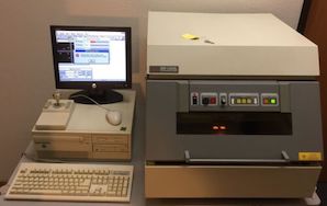
Q. I am a new engineering engineer in chip resistor (surface mount devices) industry. Now I need to seek the root cause of a defect which randomly occurs during electroplating (Ni and SnPb plating) process. The defect only can be seen after solderability test or leaching. The defect looks like a big hole at the center of terminal site of the chip. When I am using X-ray to measure the Ni and Sn thickness I found there is no Ni and Sn on the terminal site, we only found base material (NiCr) with thickness 0.22 microns. We face this problem more that 2 years and try many ways but still cannot solve this problem. Can anyone out there advise me?
I want to know what is the industrial recommended thickness for Ni/Au electroplating for surface mount devices of size 0603, 0402 and 0201. Can anyone out there advise me?
Thanks,
- Johor Bahru, Senai, Malaysia
2003
A. Hello Ho,
Hope you are doing sputtering on the edge termination of chip resistors. It seems the void (as you say) is covered by thin layer of plating and gets leached out during solderability or leach test. The probable cause is contamination on the surface of base metal. Check your handling or check your pre-cleaning process. 3-5 microns of plated nickel will withstand solderability and 1 min leach test. To prevent Nickel from getting oxidised you can apply 0.5 to 1 micron of Au flash. For 0201, 0402 and 0603 the above should be good.
Good luck,
electronic components - Norwood, Massachusetts
Q. Thank you for your advise. I use 96% sulfuric Acid to do pre-cleaning in 6% sulfuric acid tank, it is enough to do preparation before plating nickel on sputtering surface (NiCr).
W.Y.Ho [returning]- Johor Bahru, Senai, Malaysia
A. Hi,
5-10% Sulfuric acid should be sufficient enough to activate the surface, but it will not be able to remove any mask or organics which come into contact after sputtering. Do you use any mask during sputtering process? Check for contamination getting onto the surface; if those are not removed you will have voids like these.
Good luck ...
electronic components - Norwood, Massachusetts
Q, A, or Comment on THIS thread -or- Start a NEW Thread

